
Twin coils with SIDAC
IGBT (SISG) supply 2009
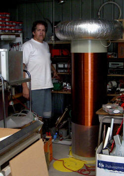
This project describes building
two identical Tesla coils and driving them with a solid state driver.
The principles of the SISG driver are described in the two following
topics after this one.
 (click to enlarge)
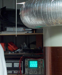
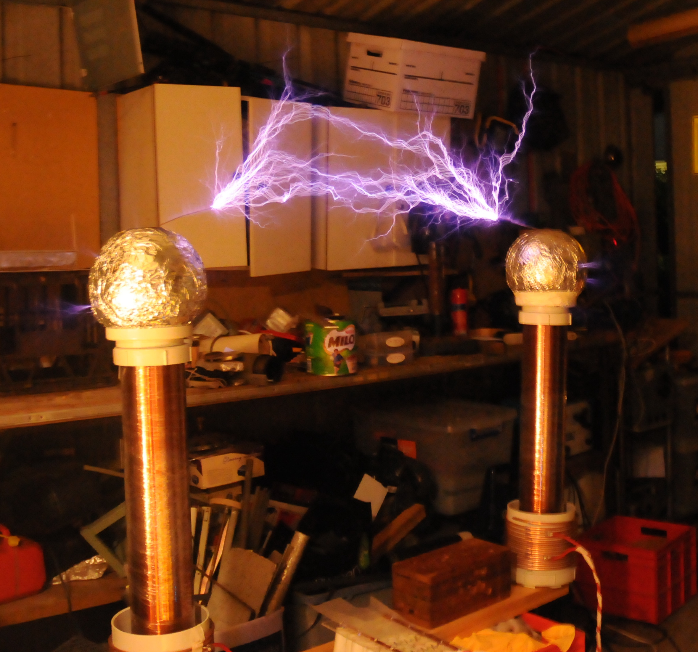
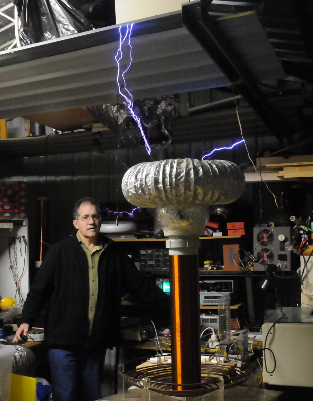
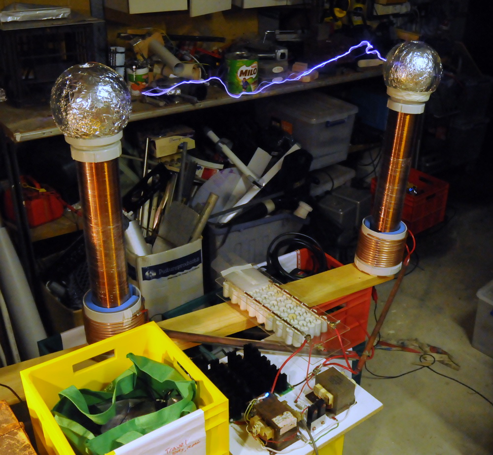
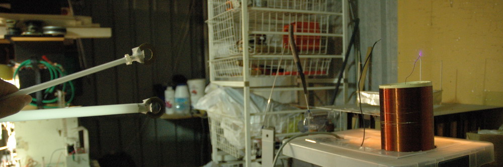
The twin coils firing above with about 80 cm spark from two 50 cm
secondary coils. This is only running on about 60 - 70 % of full
voltage due to a problem with some of the SISG modules.
(click to enlarge)
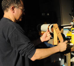
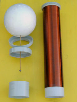
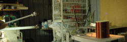
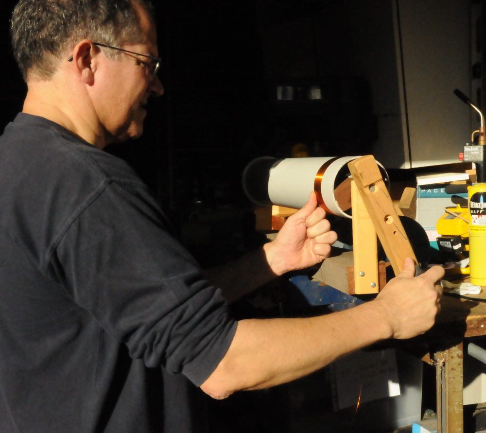
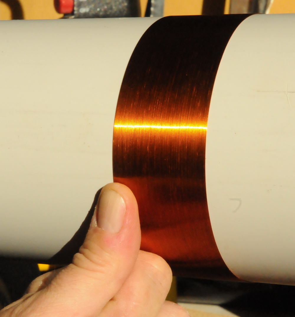
Above shows the winding of the 1260 turns on each secondary using thumb
guidance and a manual winder. Then it gets a couple of coats of
polyurethane (common timber floor sealant). Specs; 1260 turns 26 G 0.40 mm
(.016 inches) over 50.5 cm on 11 cm diam 57.8 cm length 3.5 mm thick PVC
(between 5.0 cm to 57.5 cm.
 (click to enlarge)
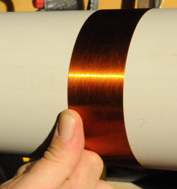
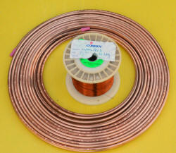
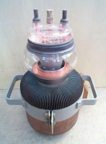
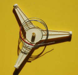
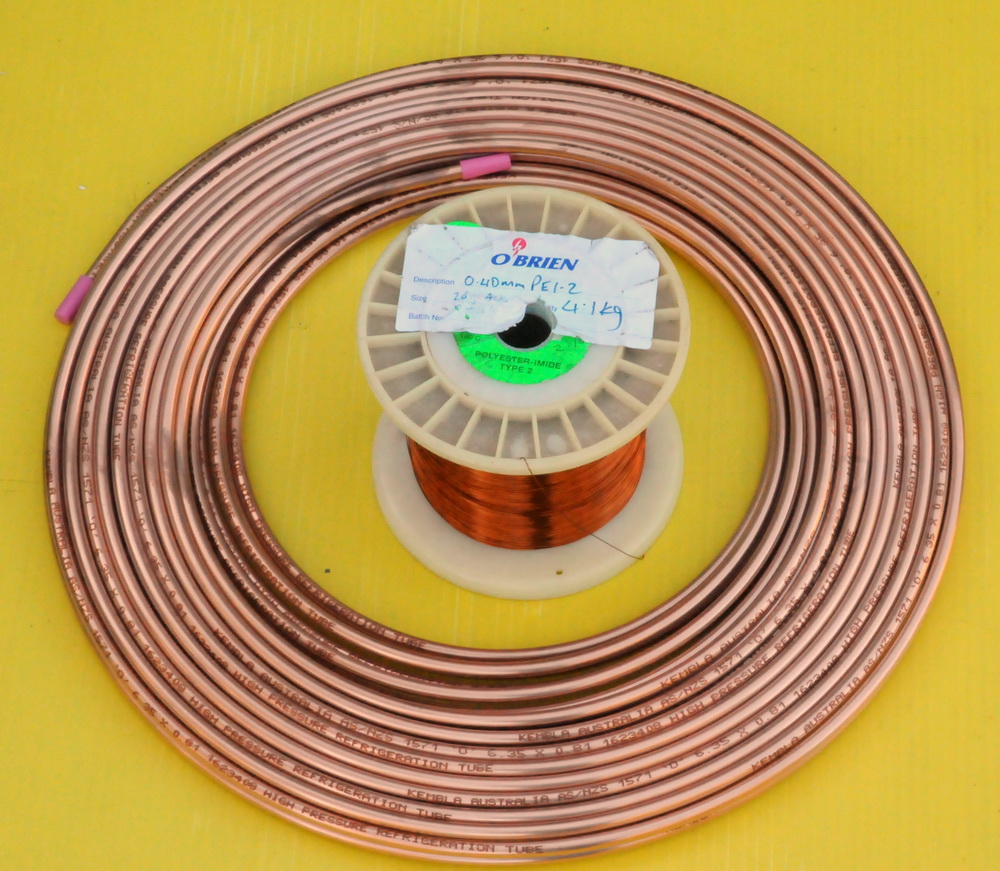
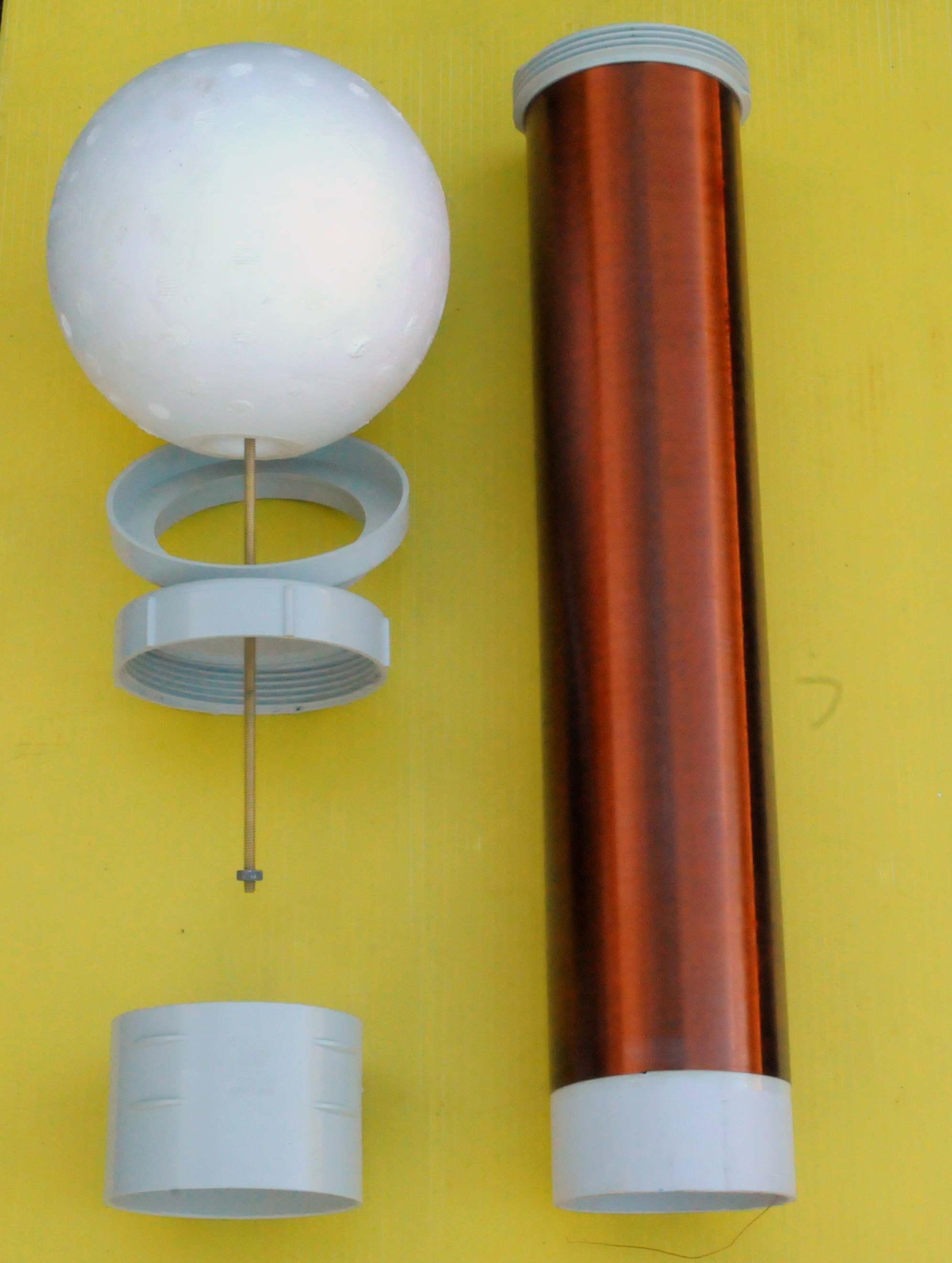
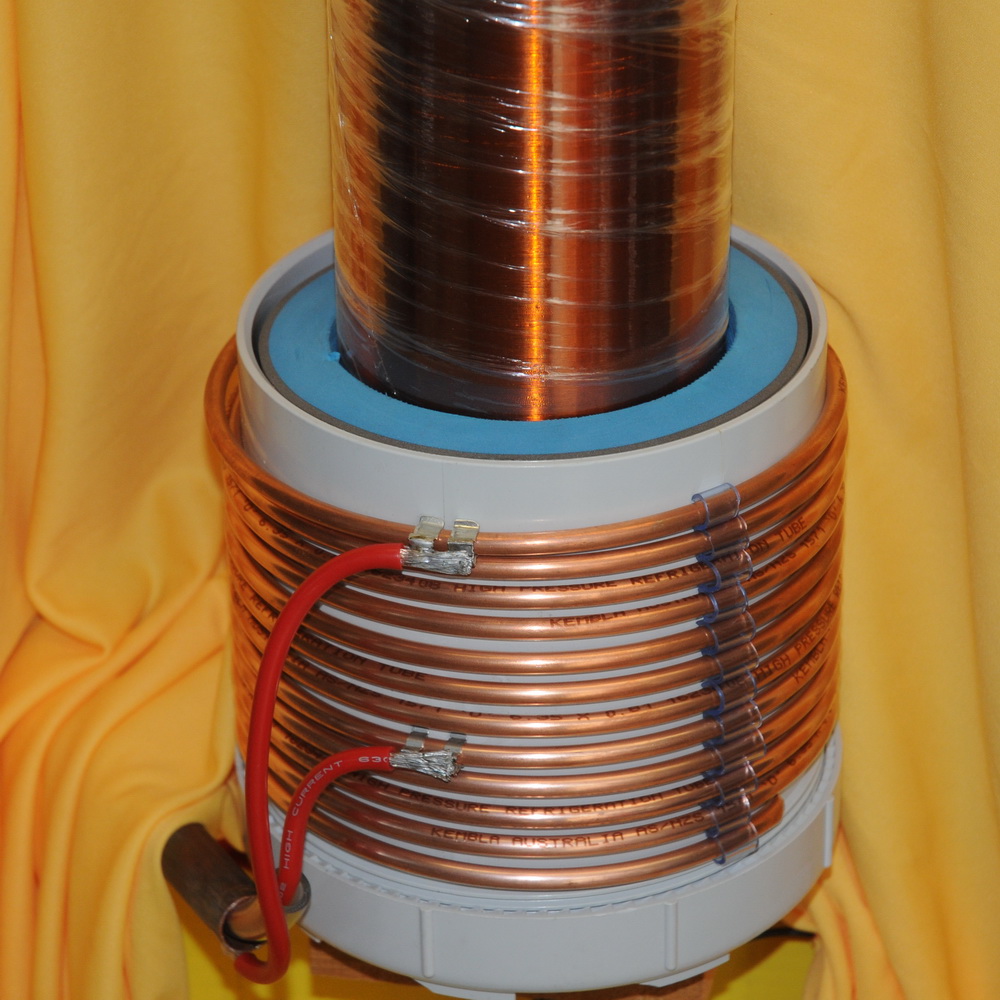
Above shows the 1/4 inch refrigeration tubing used to make the primary
and the fine polyimide coated high temperature magnet wire for the
secondary. The temporary 8 inch plastic float is coated with aluminum
foil and is assembled with some PVC connection and screws on the end of
the secondary. I am trying to keep this relatively easy to
dismantle for travel and repairs.
 (click to enlarge)
The primary coil above is unconventional as I am using a cylindrical
coil rather than a flat helical one. It was wound in minutes, is easily
spaced and tapping is with fuse holders and heavy flexible multi strand
wire. I can tap both ends. Once I get the best results by adjusting the
number of turns, I then go up or down with the same number of turns.
This adjusts the coupling to further optimize the spark length. I must
admit this is a lot more adjustable, faster to wind and more compact
than a helical coil. Most spark gap coils use a helical primary
and most DRSSTC solid state coils use a cylindrical one as they work better
with higher coupling. I am using copper pipe as a coax line to get
the power from the tank caps to minimise losses.


(click to enlarge)
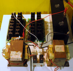
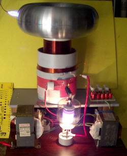
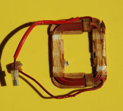
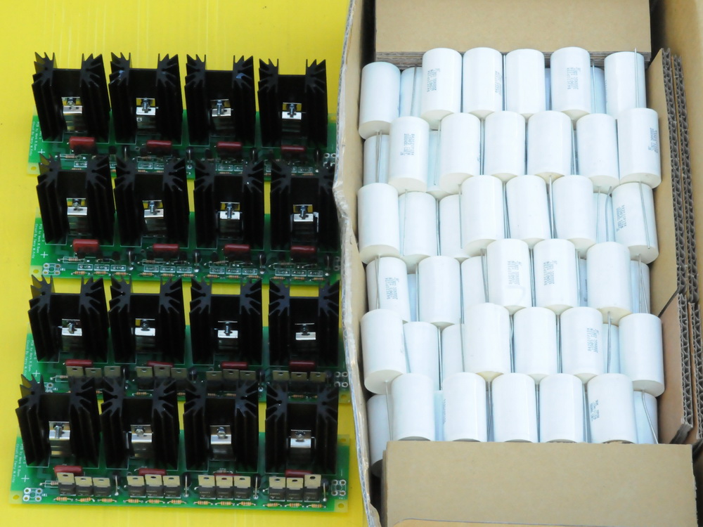
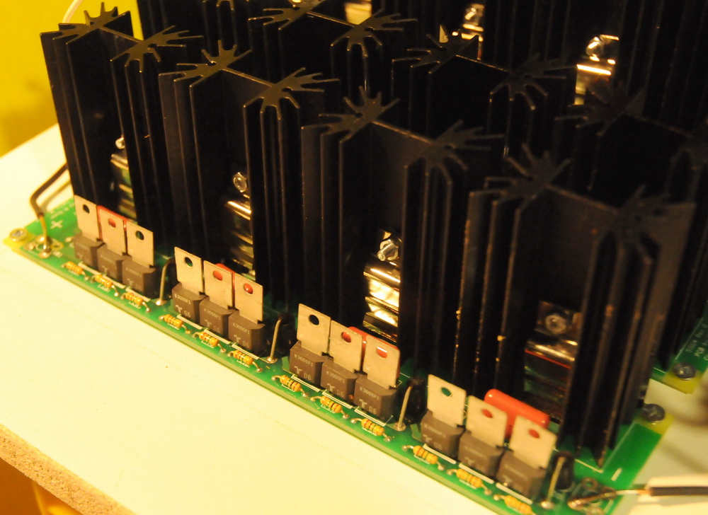
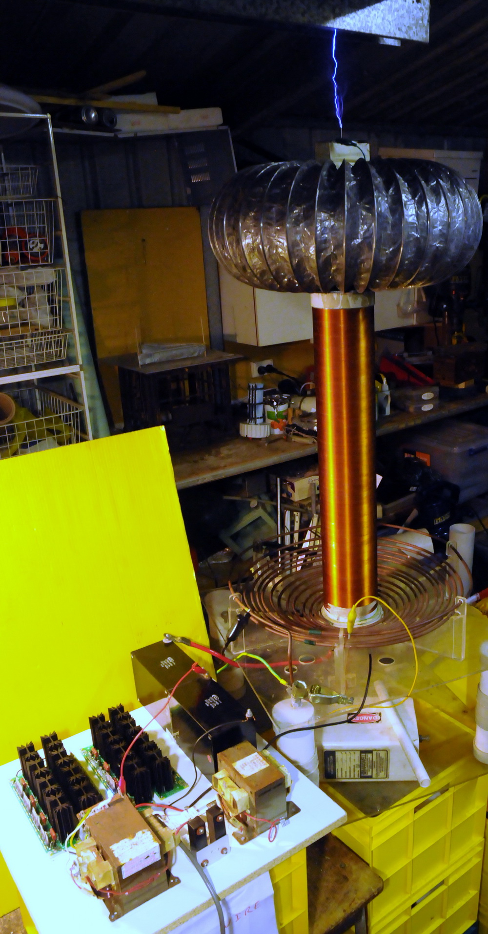
Above shows the SISG driver boards where each 900V section has its own
IGBT with heat sink triggered by 3 x 300 V SIDAC's. Total of 4 boards
with 4 sections giving 14.4 kV firing voltage. The supply is from
two MOT's in a clever voltage multiplier arrangement where the tank cap
doubles as the multipliers caps to generate over 12 kV.

(click to enlarge)
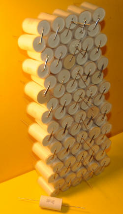
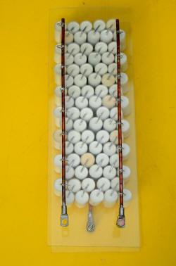
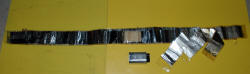
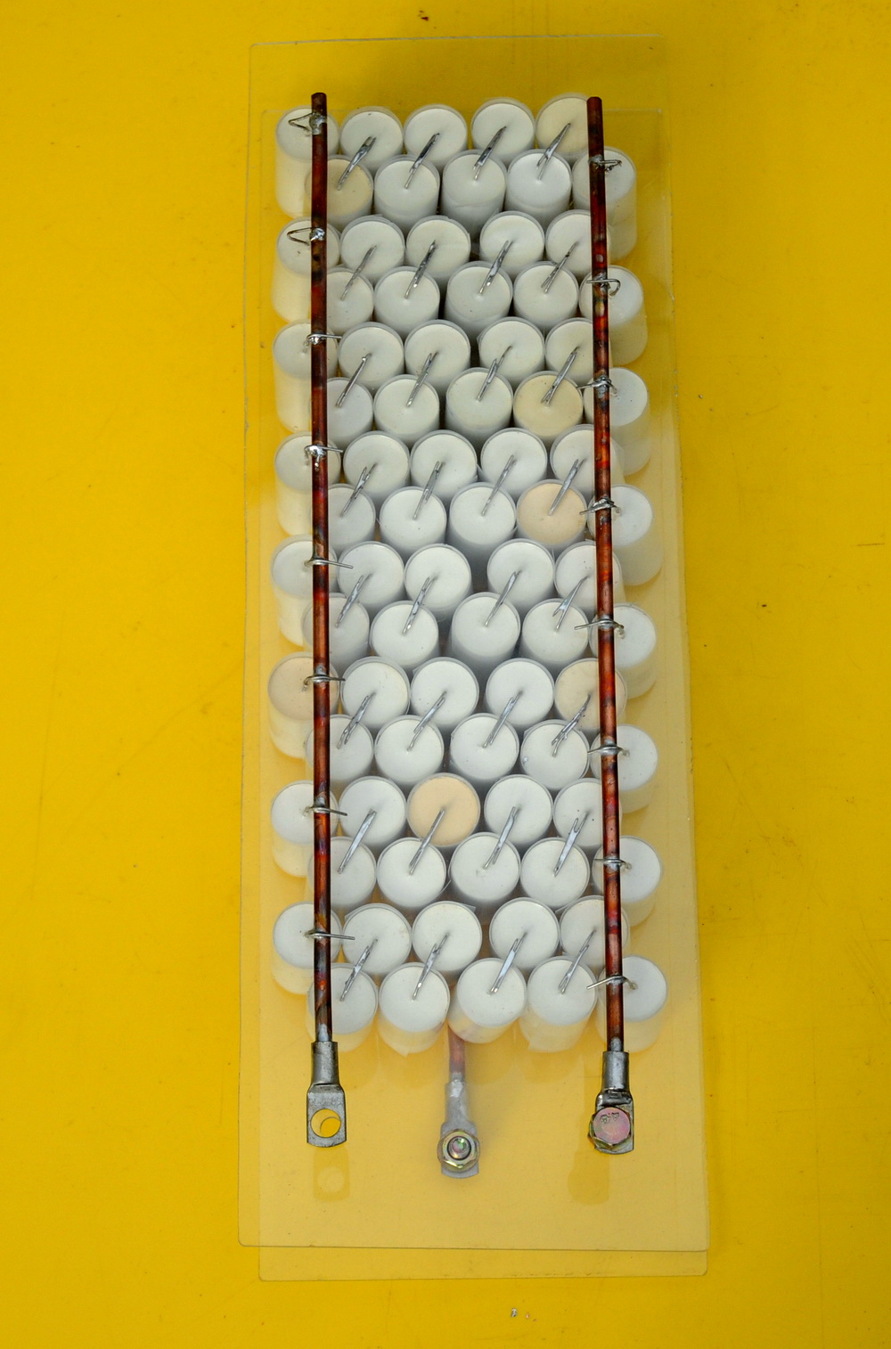
Above shows the 80 capacitors in 8 strings of 10. The capacitors for
this voltage multiplier set up need to be center tapped. As I am not
expecting a significant temperature rise and needed them to be very
compact I individually wrapped 3 layers of polyethylene around each of
the 80 caps so they could be touching and still stand off a maximum of
4kV between them. So far so good. I am only using 60 caps at present. I
am not using resistors across each cap or even across the whole bank as
the voltage in circuit decays in about 5 seconds.


 (click to enlarge)
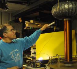
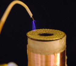
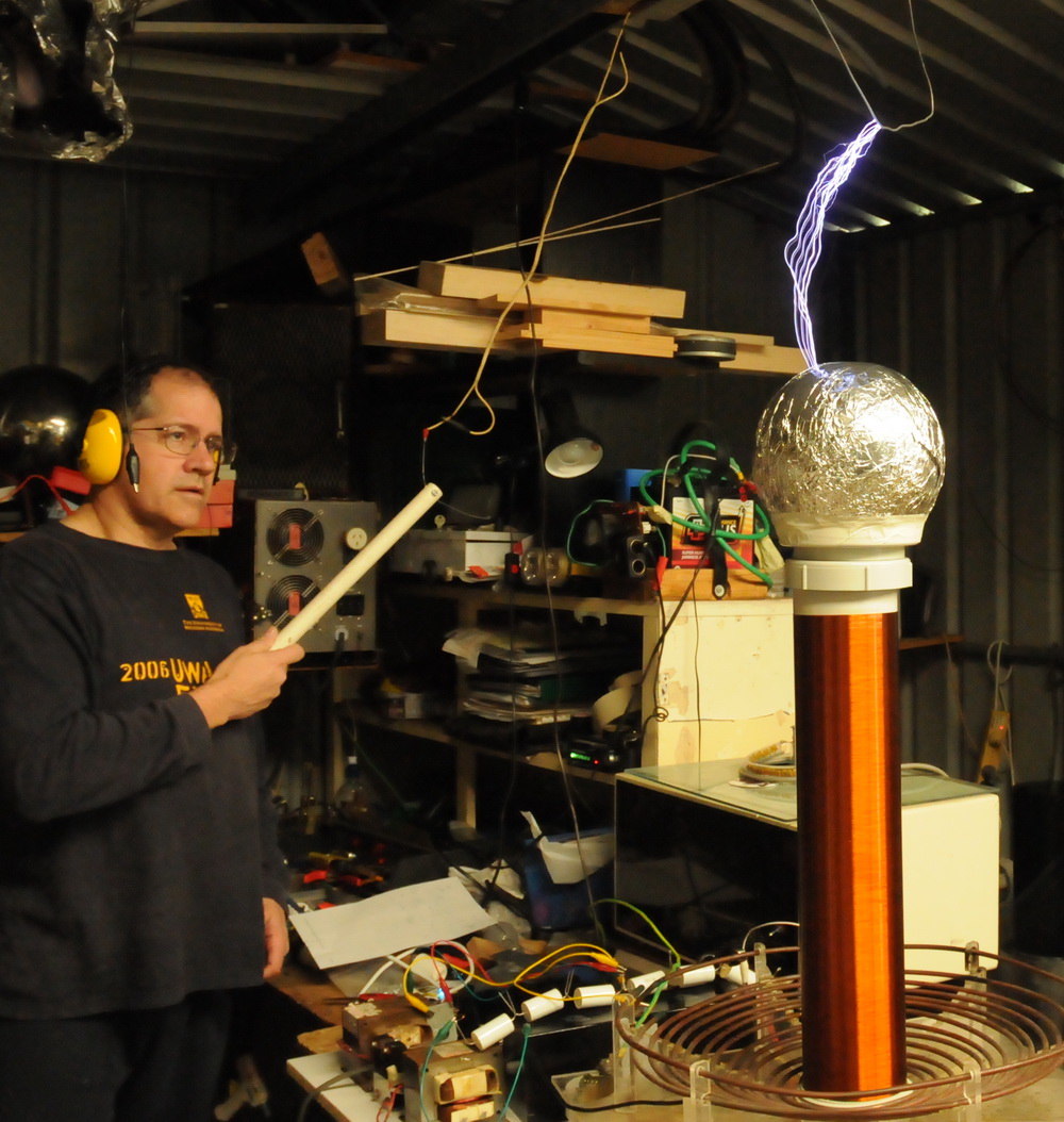
Above shows initial low power runs with a puny 1 cm spark. After tuning
and boosting power the output rose to sparks up to 60 cm from a single
50 cm coil.
 (click to enlarge)
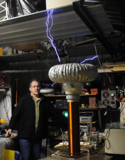
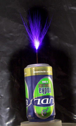
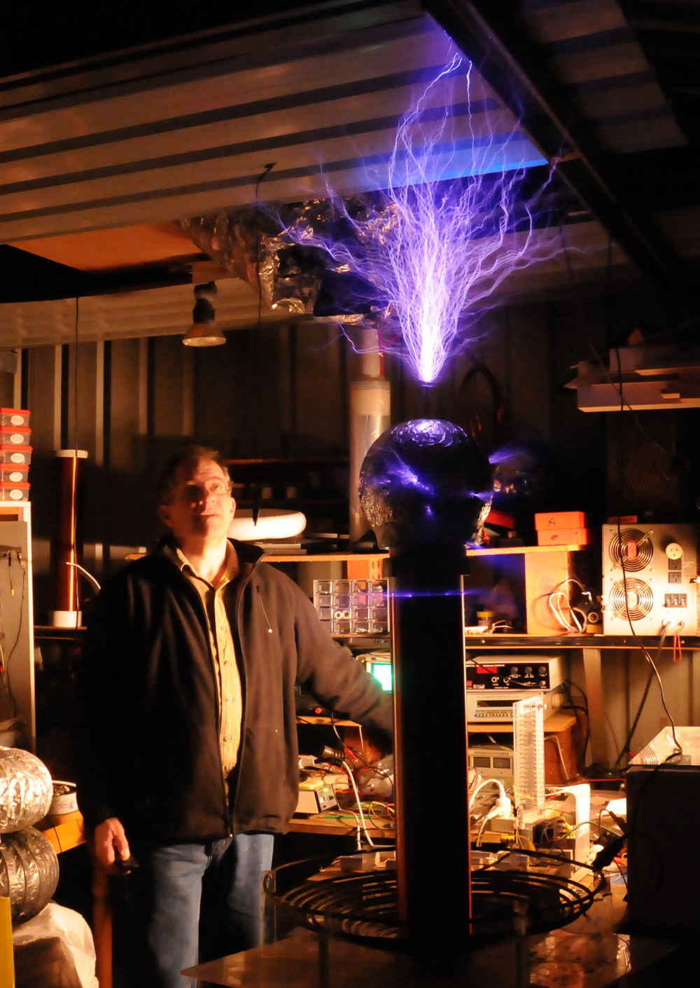
Above are the twins in action. Currently giving about 100 cm sparks
between the coils. Still not fully optimized and hope for more.
Sparks are purplish rather than bright white due to the relatively low
capacitance of the spherical topload.
A few references which describe the electronics.
http://drsstc.com/~sisg/SISG.pdf
Terry Fritz's write up of the first single MOT SISG system. This
system generates 30 inch sparks but would be better optimized with a
lower resonant frequency and bigger toroid
http://drsstc.com/~sisg/files/BigSISGCoil/
Lots of SISG related files from Terry Fritz.
http://deanostoybox.com/hot-streamer/temp/PRIANHA-III-too-early.gif
The circuit diagram of the 2 MOT Piranha system.
http://www.teslaboys.com/SISG/SISG4BOM.pdf Parts list for 1 board
http://www.classictesla.com/photos/sisg/sisg.html
Bart Anderson's SISG coil
SIDAC spark substitute solid state Tesla coil. (SSSSSTC)
2005
This is my earliest use of electronics to drive a Tesla coil. It is a proof of principle coil rather than a big performer. It uses
SIDAC's in place of a spark gap (As I use them which is with the tank
cap across the supply rather than the spark gap across the supply).
These are symmetrical breakdown devices.
As set up at present it is driven by a MOT transformer with the
associated 11 kV diode and 0.95 uF 2 KVAC cap wired as a voltage doubler to provide
5.6 KV or so. This is dumped by a SIDAC or
rather 22 in series each shunted by 1 megOhm. Each SIDAC is rated to
breakdown at 240 V and has a 1 A RMS or 20 A pulse capacity. The string of
22 SIDAC's will nominally breakdown at 5280 V. SIDAC's act similarly to a sparkgap.
Data is
here. The
SIDAC's cost US$1.33 each in 10 quantity at
Digikey.
Also shown running ignition coils (with much better performance)
here. This might
have application for small coils running low voltages where spark gaps
become problematic, but without the complexity of an SSTC.
 (click to enlarge)
Pic shows 2 inch sparks on my 4 inch coil (5 kV in 60 kV out). I later
used 47 SIDAC's each shunted with 1M
 .
I could get small streamers but not much more regular spark length.
However, if I used a spark gap in series with the SIDAC's the spark
length increase was marked and over 6 inches. I interpret this to
indicate that quenching is not really happening with the SIDAC's alone
possibly due to the speed of the devices. I had hoped the SIDAC's
recovery when the current drops would do this but apparently not well or
fast enough. Di/dt is 120A/uS.
.
I could get small streamers but not much more regular spark length.
However, if I used a spark gap in series with the SIDAC's the spark
length increase was marked and over 6 inches. I interpret this to
indicate that quenching is not really happening with the SIDAC's alone
possibly due to the speed of the devices. I had hoped the SIDAC's
recovery when the current drops would do this but apparently not well or
fast enough. Di/dt is 120A/uS.
SIDAC IGBT Spark Gap
(SISG) 2006
SIDAC's are now being used as the triggers for IGBT's to act as a spark
gap with fascinating and evolving information being developed by Terry
Fritz here. Each driver
fires at 900 V to be within the IGBT 1200 V rating. Multiple drivers are
simple daisy chained to reach the desired firing voltage eg 12 kV NST
requires 16 stages which adds to cost. However it does open the way for
using lower voltages in the MOT range where real spark gaps don't work
well. Terry has reached 30 inch sparks with these and Mark has
reached 40 inches. Hot off the
press May 21 2006!
 (click to enlarge)
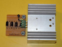
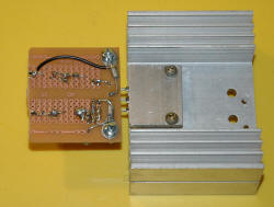
Here is my SISG driver. No I don't have a PCB and yes some of those
components are vertical. I have built it on part of a multikV strip of
SIDAC's that I have cut off.
Nevertheless the fast components have very short paths and should have
low inductance and reasonable current rating. The IGBT fits nicely into
a terminal block to allow changing IGBT's as I want to try some big
IGBT's later. The heatsink was chosen for it's extra holes rather than
need for size. An extra aluminium plate allows the IGBT to be secured.
The black wire allows selection of the number of SIDAC's to use.
 (click to enlarge)
This shows a very rough setup with (almost) 2 turns on the primary and
an SISG running at 900 V with 120 nF resulting in a 1 inch spark.
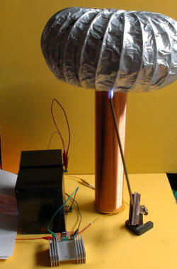
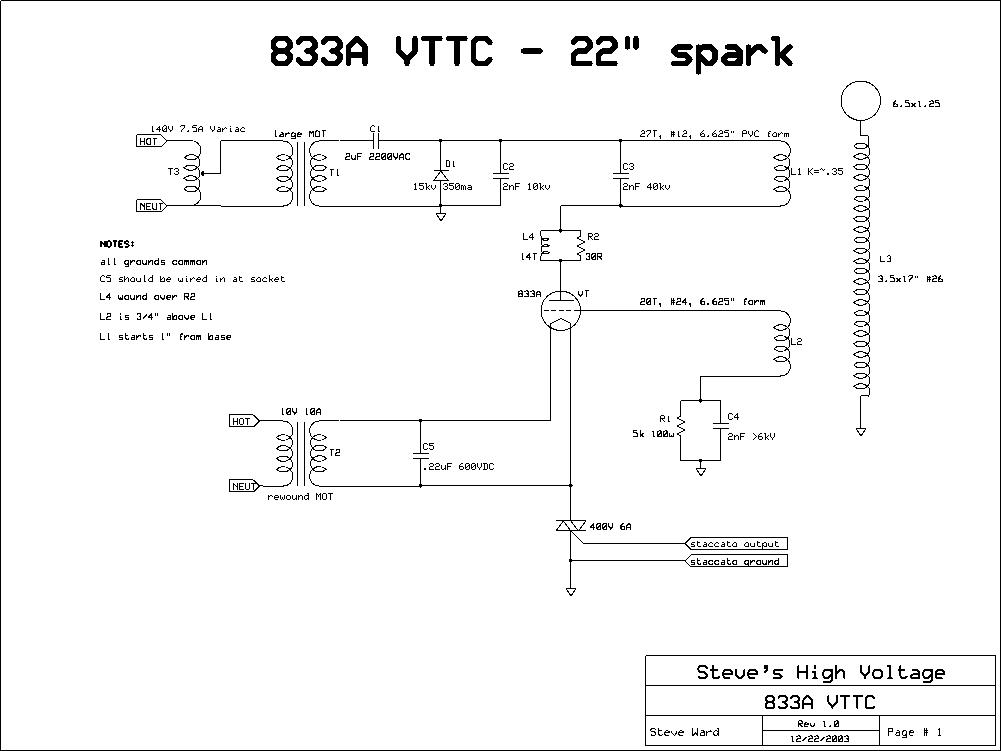
Vacuum tube Tesla coil (VTTC)
2005
This is a version of a Tesla coil where the primary is driven by a
vacuum tube (valve)
oscillator. I have a Philips TB3/750 power triode rated at 3
kV 1 kW with a 5 V 14 A filament. The high voltage comes from a
microwave oven transformer (MOT) and doubler. The filament supply is from a
rewound microwave oven transformer to give the 5 V. This is largely a
copy of Steve
Ward's VTTC modified to use parts I had on hand.
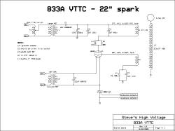
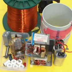 (click to enlarge)
Above left shows Steve Ward's circuit diagram. The 833A
valve is a bit more powerful then the one I have. Above right
shows the parts scrounged from my shed. I haven't had to buy
anything specifically for the coil at this stage. I was donated this and
some other valves by Prof. David Blair (Physics, Uni of Western
Australia).

 (click to enlarge)
Above left shows the base of the VTTC. Left MOT is for the main HV
with a diode voltage doubler using one of the 3 MO capacitors. Right MOT
is the filament supply. Vacuum tube socket is front centre and MO
suppression filters at rear for each of the two MOT's. Centre photo
shows an early shot in action. This is not in tune and is only
using a single 440 pf tank capacitor instead of the 5 I would need to
get around 2000 pF (= 2 nF). This allows the rather small
secondary coil to run with a relatively large toroid (the only one I
have that looks decent close up). Right photo shows the
tube glowing a bright orange. In this setup it is very
inefficient.
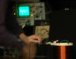
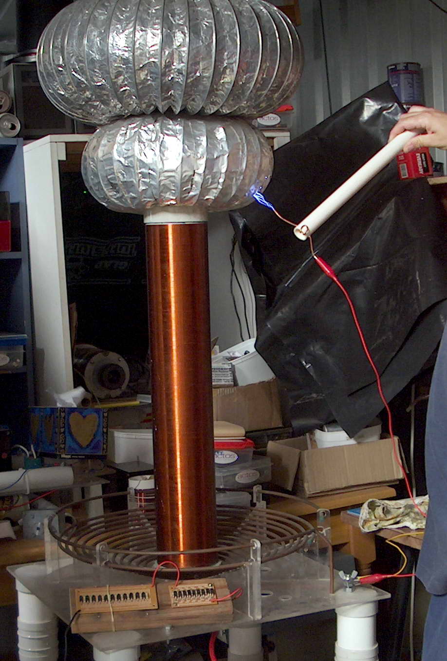
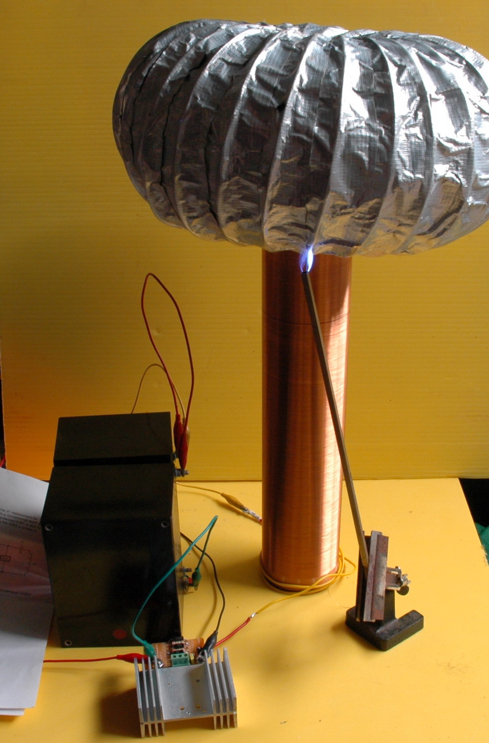
A further step along the way. Still not in tune but with streamers up to
4 inches. Frequency is about 300kHz but with a 2MHz harmonic. I have a
12 inch secondary with about 750 turns of 26g. No staccato yet but I
have the parts.
 (click to enlarge)
Photo shows a drinking man's toroid and some sword like streamers.
Vacuum tube is not red (well, for short runs at least).
Liviu Vasiliu has a
database
of VTTC coilers and their sites.
For a really big VTTC I have acquired a
large 60 kW 30 Mhz transmitting triode that runs on 12 kV and has a filament
current of 89 A.
Royer
circuit
2005
Details of this driver driving
flyback and other coils are
here. Here it
is used with a 1+1 turn primary on the base of my 18 inch coil.
 click to enlarge
Solid
state variac
2005 A variac is a variable transformer used to supply
adjustable power for many projects and is invaluable. They are
also expensive as they are large and heavy. Here, I explore the
solid state option which may be preferable in some situations.
This SSVariac I lashed up uses an IGBT out of an inverter microwave run
by a TL494 at 2kHz. The tricky part is that it is "inside" a bridge
rectifier so that it controls AC. This is inserted between the mains and
the NST. There is also a snubber of 0.1uF and 400
that gets pretty hot. I haven't tuned this for long term runs yet as a
lot of power is still being dumped into a 230V MOV across the IGBT.
(Fortunately I have 300 of these)
 (click to enlarge)
Pic shown full on running one half of an NST. You should be able to
follow the wiring setup from the photo
 Yes I am turning an "old fashioned" variac but just to supply power to
the setup.
Yes I am turning an "old fashioned" variac but just to supply power to
the setup.
I don't really think that it would be more expensive than a variac for
NST use of less than 5A 240V. The main rectifier could be 3A diodes,
and the IGBT/Mosfet could be almost any one with a 500V rating at 10A.
The TL494 circuit could be a 555 in this situation. The snubber may
generate some heat and a mains filter is probably wise. A small 12V
transformer or even old 9V plugpack could supply power. As ususal it
depends how much can be scrounged up.
If this can be made to work reliably and effectively then it may be of
interest to those who use NST's.
Tesla coil made only
out of parts from a single microwave oven 2006
Ok, I reckon that there is not enough ingenuity and resourcefulness
going on in budget coiling these days.
So,
on the 4HV forum, I proposed a prize of $US 50 to be paid by me to
the person who makes a Tesla coil with the longest sparks from a
standard microwave oven.
 (click to enlarge)
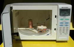
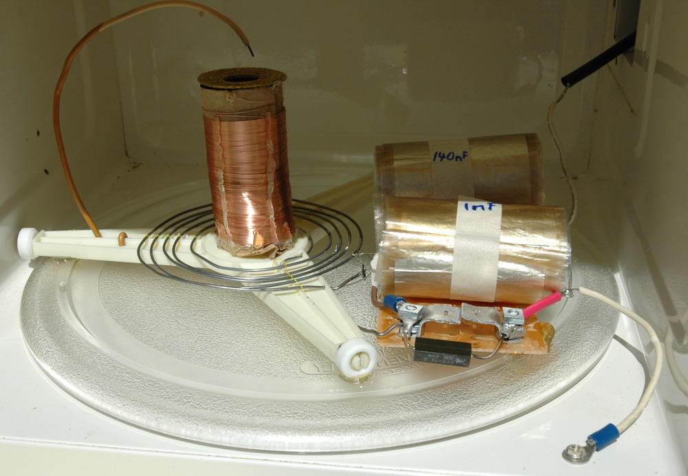
Above, a standard microwave oven with lid off.
The rules were:
One standard domestic MO (microwave oven) less than 1000W to be obtained
free.
MO must be the transformer type not the inverter type.
Only the parts of one oven to be used. No
other parts to be used apart from solder, hot glue or epoxy in
reasonable amounts (not large amounts to make secondary formers).
This also means no PVC, tape, paper or other extraneous substance.
How you adapt the internal parts is up to you.
Progress, results and sparks must all be photographed to confirm use of
only parts of one MO are used. Spark length measured from the photo with
a ruler adjacent.
And the result? Well no one won it. I didn't get the time to
complete mine before the deadline. However I have done it - just 9 days
late. Shown here with 1/2 inch sparks only but best in development has
been 1 inch and plenty of scope for improvement with better design.
Here's how:
Power supply is the MOT. This needs
current limiting and this is achieved with a 150nF capacitor and the
voltage is boosted by a one stage multiplier using the MOT diode to give
4kV peak. Note that power is taken off across the diode not across the
cap to get the voltage multiplier effect. Hey what's this about a 150nF
cap? Where is that in a microwave oven? Well that is the key to this
project. The 1uF 10kV DC mylar and oil cap (that is in all non-inverter
MO's) needs to be taken apart and unwound. Lengths of the multilayered
dielectric and foil are taken out and cut to length. It took about 10
feet of the windings to make 150nF. This is perhaps only 30% of the
total. New electrodes were added.
 (click to enlarge)
Above, shows the mylar cap drained of oil and unwound, then rewound with
4 redundant layers for the tank cap.
Tank cap. This is a 1nF cap. The
technique is similar but I retained the original electrodes from the cap
to use in this section as they were better suited to a high current.
Construction of this cap was different in view of the much higher
voltage/current and frequency stresses. It used about 30% of the length
of the cap windings. The plates were only about 1 foot long by 2 inches,
however I used two sections of foil/dielectric between them. The foil
was not connected and was kept to equalise voltage stresses. All in all
something like 12 layers of mylar and 2 foil layers separate the main
electrodes.
Being mylar they do warm up a bit.
Spark gap This is two aluminium
electrodes (from the frame of the MO fan) bolted to part of the MO timer
circuit board with all the components and printed circuit ground off. It
really needs another section to give better quenching.
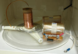
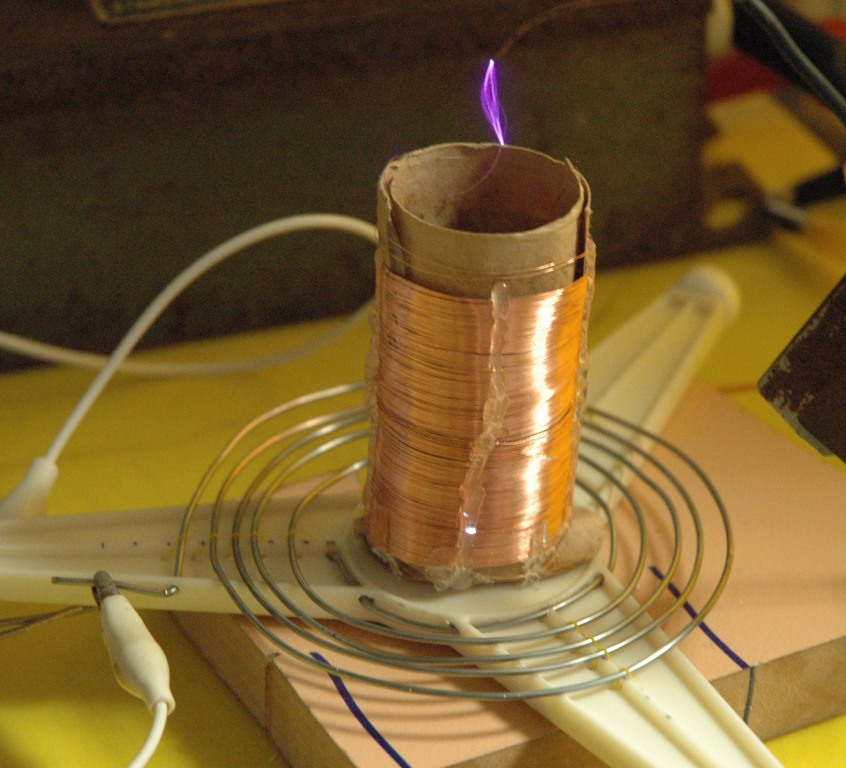
Primary is the MO transformer 6V winding
which is heavy copper. This is stuck on to the 3 legged wheeled frame
that the glass food tray sits on and rotates.
 (click to enlarge)
Secondary former is the cardboard
internal cardboard insulation from the HV cap. It was washed but became
a bit soft but still usable.
 (click to enlarge)
Above shows the primary former being HV tested for conductivity.
Secondary windings use wire from the fan
motor and less than half was used. The hot glue didn't stick the
cardboard former together properly and the windings slipped and
overlapped. I have had some interturn shorting (and may still have) so I
can't really push the power much without a rewind. No idea how many
turns.
Toroid I did try winding lots of turns of wire on the fan blades but it
didn't improve the performance. so I just left the metal mesh spacer
that sits on the output of the magnetron for a nice colour.
 (click to enlarge)
Photo above shows a spark with inter-turn shorting and also a racing
spark suggesting over-coupling.


(click to enlarge)
Left photo above shows the full setup with the MO transformer
feeding into a voltage doubler formed by the 150 nF cap and diode.
The output is taken across the diode to get the voltage doubler effect.
This means the diode is across the spark gap which does look unusual but
it should give 4 kV peak to fire the spark gap. The tank cap is 1
nF. The center photo shows sparks of up to 1 inch from it
from a 4 kV NST and a 2 gap static gap. The right photo shows the
completed coil running from the MOT. Not fabulous performance but the
proof of principle is there are plenty of opportunities to do better. I
was reluctant to retune and push harder as the 150 nF cap kept blowing
and having to be rewound with a section cut out. The secondary is
overlapping and may not tolerate a higher voltage although I suspect it
may have a properly shorted turn already which is why performance has
dropped despite the power increase.
 (click to enlarge)
And finally put back in a MO with the electronics still functional so
you push START and STOP to run it!
Hand-cranked TC 2007
This was just a quickie to demonstrate that one can get sparks with a
hand cranked generator.
I used an antique telephone alternator and was able to demonstrate
sparks about 1/4 inch when cranking out about 100V AC peak into an NST.
Mains is about 375 V AC peak by comparison. I used only one rather than
4 segments of the static gap but other wise my
mini-TC was unchanged.
 (click to enlarge)
Above shows a tiny spark in series with a neon on top of my mini coil.
My right hand is a blur of rotation and my left hand is holding the
camera infrared remote (which the camera can see). The out of
focus CRO is set for 50V per division ie just over 100 V peak in a
rather odd shaped wave.
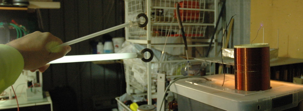
Neon
and Fluoro tubes 2007
This was just another quick demo of a comparison between neon and fluoro
tubes for Tesla coils.

 (click to enlarge)
Above shows a similar length neon and a fluoro tube with ends connected.
The electrode end has been made identical by using same sized
electrodes. One has to bring the neon much closer to fire it. Of course
the color is much nicer...
Tesla Tuner
2007
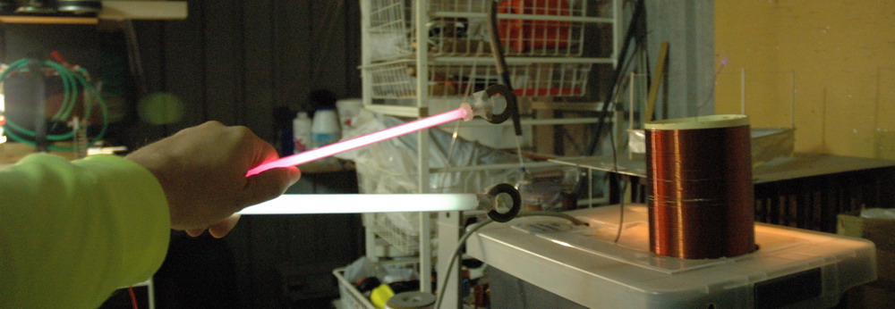
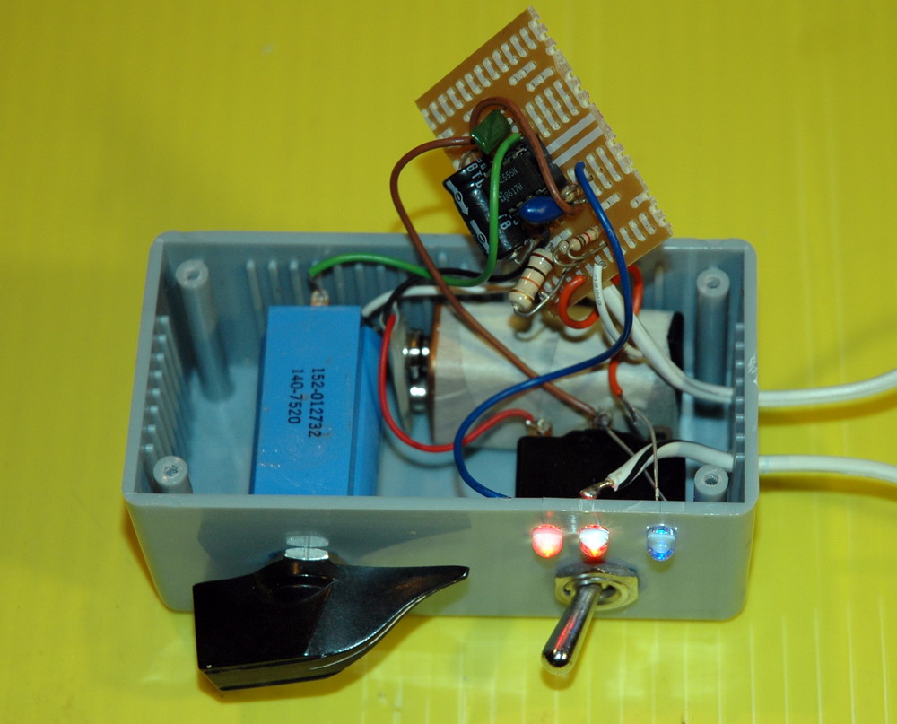
This is a handy little circuit developed by Terry Fritz and is used to
tune Tesla coils, both for primary resonance in parallel and secondary
resonance in series. It is a little 555 oscillator that at
resonance will make LEDs light up brightly. The circuit is
here.


 (click to enlarge)
Left photo above shows the internals of my version using on hand
parts. I used a 10 turn pot that I had on hand and various "near
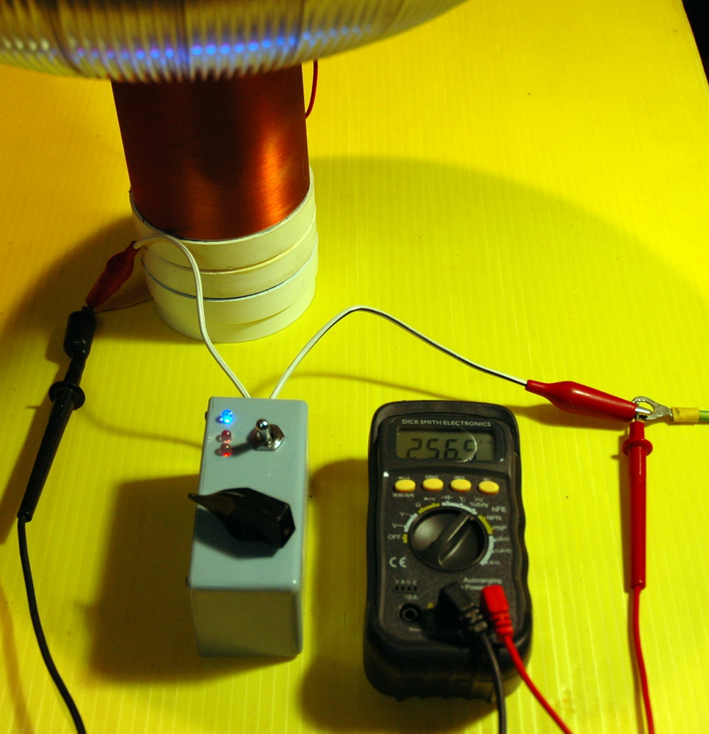
enough" parts. The center photo shows it on with the blue
LED being the power and the red LED's being the ones in series with the
output which will be brightest at resonance. The right photo
shows it in action with a frequency meter indicating 256 kHz resonance
of this small coil with large toroid. The tuner (and frequency meter)
goes between the ground end of the TC and ground. In this case the LED's
will be darkest at resonance. For my large TC the resonance was 41
kHz.


