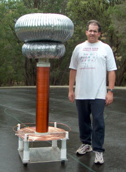
6 inch coil,
8 foot sparks
 (click to enlarge)
See the results in the
Tesla coil sparks section.
Components and specifications (Calculations using
Java TC
10.i. Capacitor calculations using
JAVAMMC)
Secondary voltage peak
can be calculated by:
Vsec = Vprimary * sqrt(
L sec / L primary)
=
11,300 * sqrt (48 mH / 21 uH)
=
11,300 * sqrt (2285)
=
540,000 V
Alternatively, assuming that all the tank capacitance energy is
transferred to the total capacitance of the secondary coil and topload
the secondary voltage can be calculated using:
Energy = 1/2 C V2 .
Accordingly the tank capacitor energy at 11.3 KV is
Energy = 1/2 (0.000000092) *(11,300)2 =
5.9 Joules
Hence if 5.9 Joules is the bang energy available then assuming perfect
transfer of energy to the secondary circuit capacitance of 45 pF:
5.9 = 1/2 (45
*10-12) *(Vsec)2
ie Vsec = sqrt (0.26
*1012 )
Vsec = 510,000
V which agrees well with the figure above. Real world efficiencies are
around 85-90%
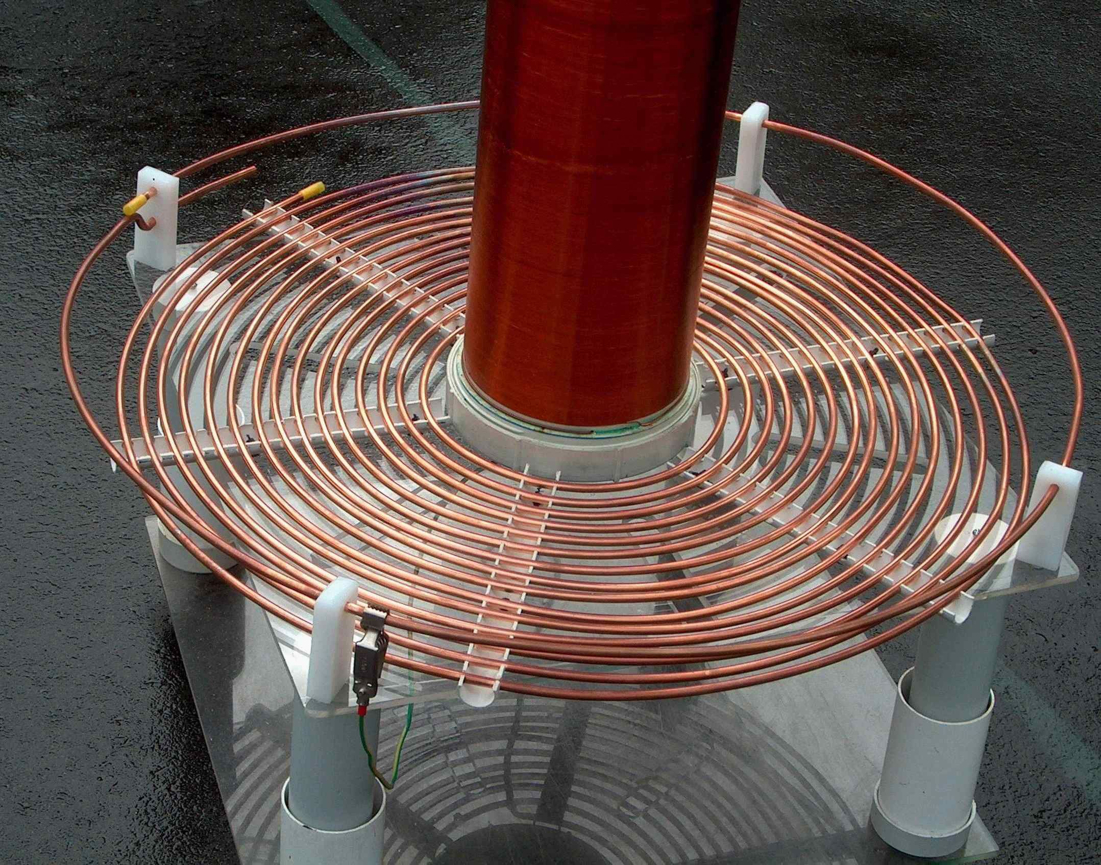
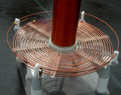
Primary: Flat 1/4 inch (6.5 mm) copper piping wound to 14 turns on PVC supports.
Tapped at around 7 - 11 turns depending on the tank capacitance and the topload.
Inner radius 8.6 inches (22 cm) with 0.6 inch (1.6 cm) per turn giving
0.4 inches (1.0 cm) between turns. Outer radius 12.5 inches (32 cm).
Calculated inductance is 21 uH for 7 turns, 47 uH for 10 turns and 87 uH for the full 14
turns. Calculated peak voltage is 11,300 V.
Secondary: 1280 turns of 24 G (0.56
mm copper, 0.625 mm average when wound) enamelled wire taking up 32 inches
(80 cm) on 6.3 inch (16 cm) PVC pipe.
This is around 2000 ft and 3 lbs of wire.
Calculated inductance is 48 mH. Self
capacitance is 12 pF. The coil is elevated 3
cm above the primary for a coupling of 0.10. This value needs to be high
enough for efficiency but low enough to allow 'resonant' action rather
than 'transformer' action to prevent voltage peaks along the secondary
which cause inter turn arcing (as on my 4 inch coil) or 'racing sparks'
directly to the secondary. Values of 0.18 to 0.22 have been quoted as
preferred which makes this coil seem suboptimal, however, coils of this
size usually use flat primaries and are marginally elevated above the
primary. Coated with
two coats of polyurethane spray on sealer. There is a PVC
screw type base to allow dismantling.
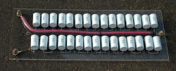
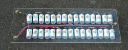
Capacitor: The initial photos were taken using the 48 nF capacitor made
with polyethylene and
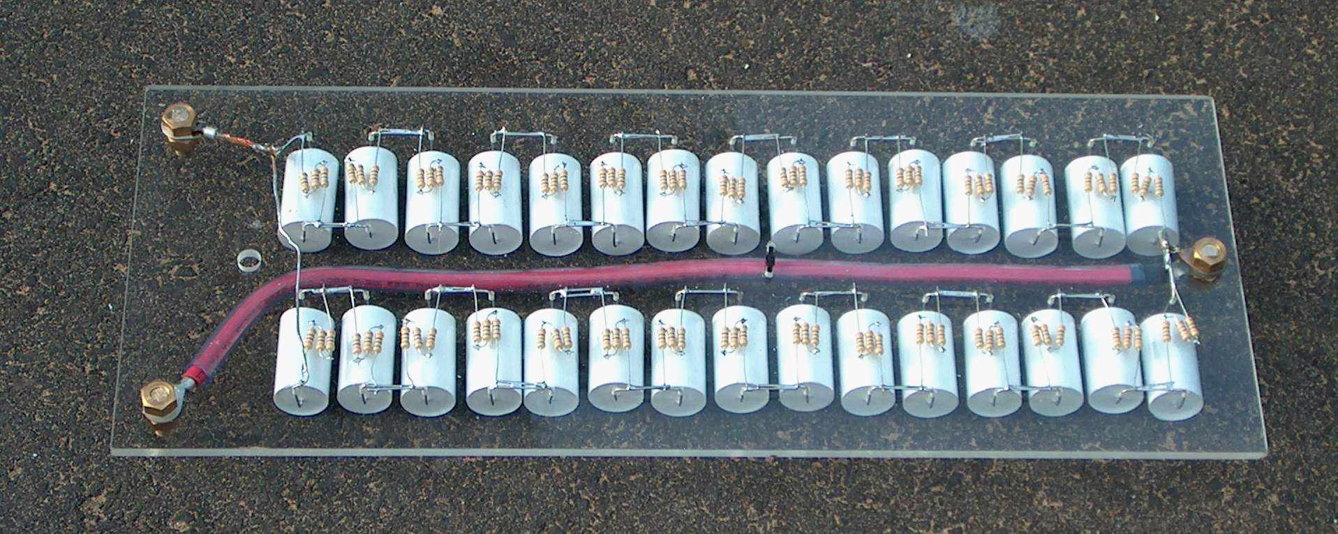
aluminium foil rolled in transformer oil. I also have used
Cornel Dubilier
capacitors type 942C 16P33K (0.33 uF 1600 v DC) in a MMC (multi mini capacitor) arrangement of 2 parallel strings of
15 series capacitors. This gives 44 nF at 24 kV DC and each capacitor
is shunted with 14 M ohms 2.4 kV (as 3 x 4.7 M ohms 1 watt, 800 V peak
rating). These are similar to the more commonly used
capacitors which are the 0.15 uF type in that range that have a
reputation for being bullet proof in this application. The
capacitors are each rated at 13.3 A RMS and 633 A peak. Dv/dt is 1919 V/uS,
ESR 15 milliohms and ESL 32 nH. In the
highest power shots I used both together for 92 nF. Peak
calculated current with 92nF is 730 A and storage is 5.9 J per bang. The MMC is
shown below. This capacitor has been installed to boost the
existing one at
Scitech science museum where it has functioned for many years.
 (click to enlarge)
Power: As before with 4 MOT's (microwave oven transformers) under oil.
Current draw with 48 nF tank capacitor is about 20 A 250 V in with the variac at about 220
V but I need more power factor correction capacitors than the
32 uF at present as the predicted is around 330 uF. The addition of 100 uF more,
however, did not seem to
alter performance or current draw in any way. I don't use any ballasting.
(Real men don't eat quiche either).
Spark gap: As before the ARSG (asynchronous rotary spark gap) uses an angle
grinder (nominal 10,000 RPM) which with a 1/2 inch Tufnol wheel
with 8 x 1/4 in bolts giving up to 9000 rpm =1200 bps. Unlike the 4 inch coil
which works best with the ARSG flat out, this one works comfortably at
about 120 bps. The stationary electrodes are
0.2 inch (5 mm) 2% thoriated tungsten. The spark gap doesn't start to
trigger until the variac is putting out about 90 V AC when gap is
minimised, increasing to 180 V AC when the electrodes are worn down.
Wiring is with 4-8 mm automotive cable.
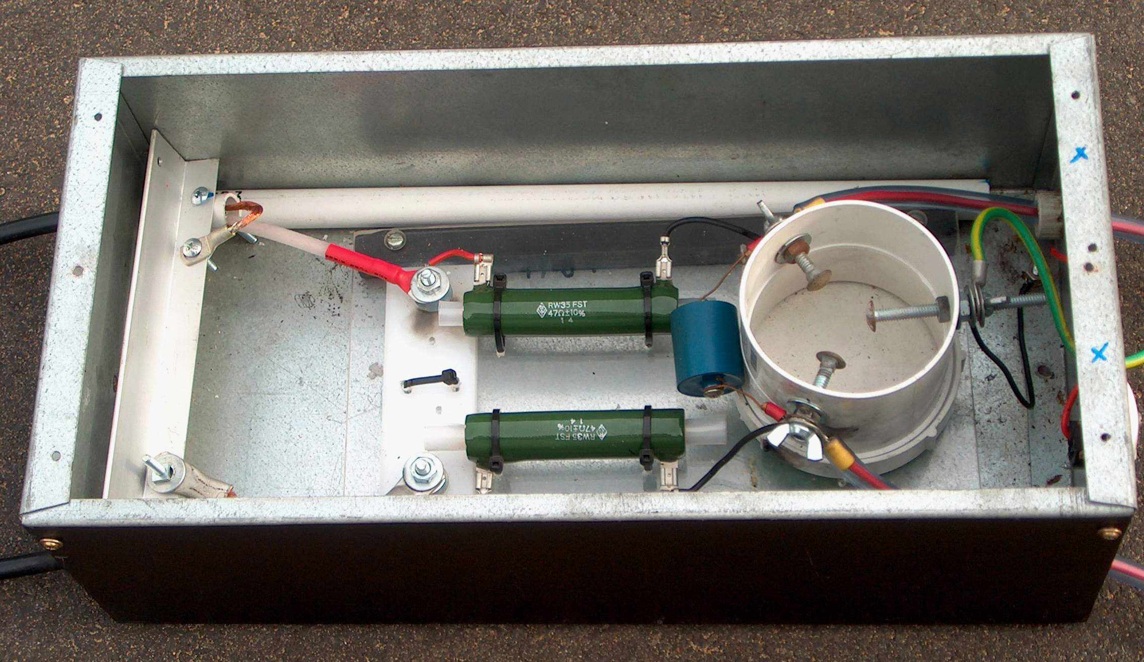
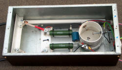
Primary suppression is with 2 x 47ohm wire wound 50 W resistors found in
my junk box to which I have added a ferrite core.
This has better insulation of the ferrite core than the previous setup.
The 570 pF 40 KV capacitor and spark gap are the same. The safety spark gap
never fires with the 6 inch coil. My later version uses MOV's to
suppress the voltage spikes and is popularly known as a Terry filter.
 (click
to enlarge)
(click
to enlarge)
Toroid is 12 inch (31 cm) duct, 29 inches (73 cm) diameter.
There is a smaller toroid of 8 inch (20 cm) ducting, 20 inches (51
cm) in diameter. The lower toroid is spaced 10cm above the upper
end of the secondary. Calculated total topload capacitance is 38 pF and
total coil plus topload effective capacitance is 45 pF.
Resonant frequency (calculated) is 109 kHz.