|
|
World's Brightest Bike Lights |
|
|
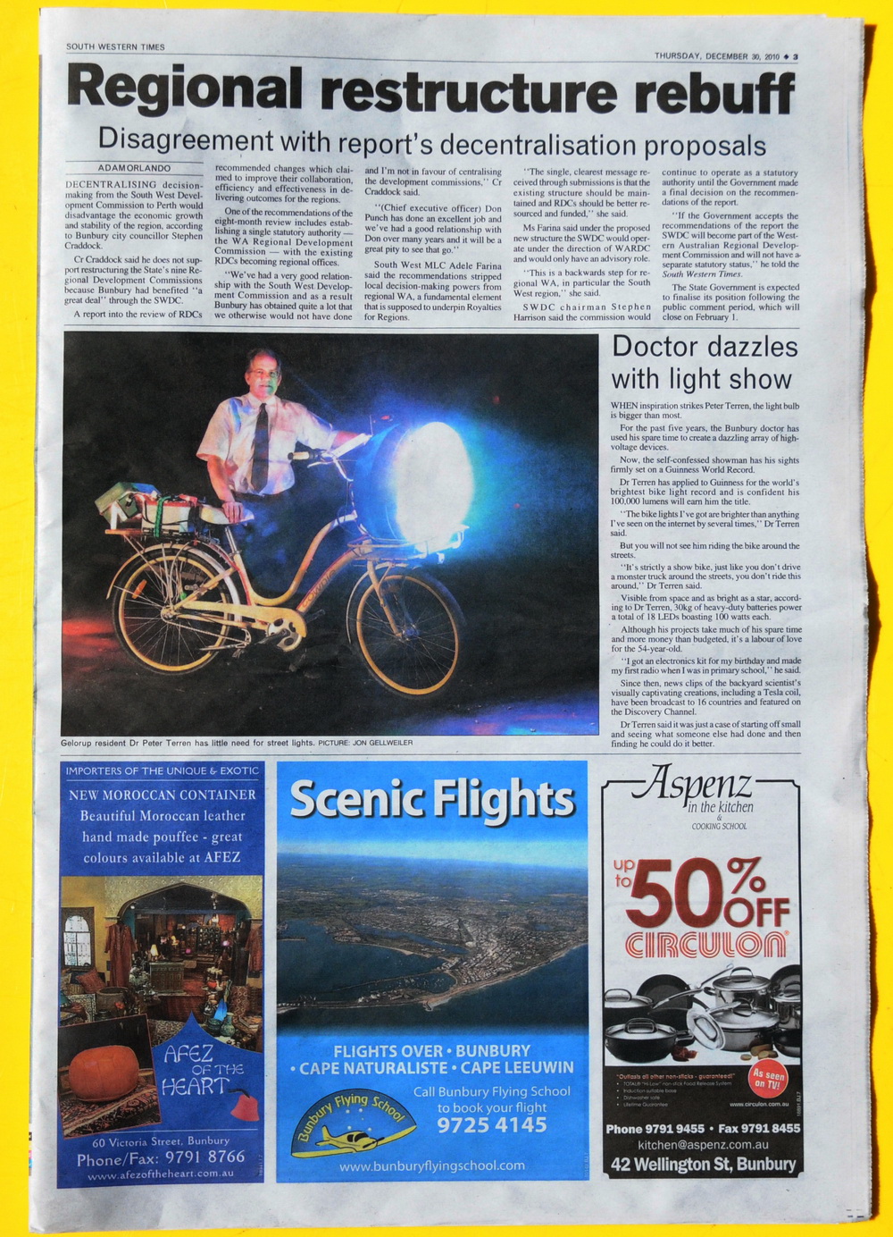
World's Brightest Bike Lights
2010
Gallery
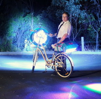
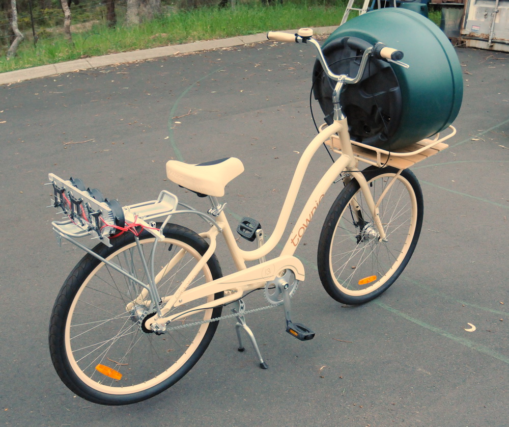
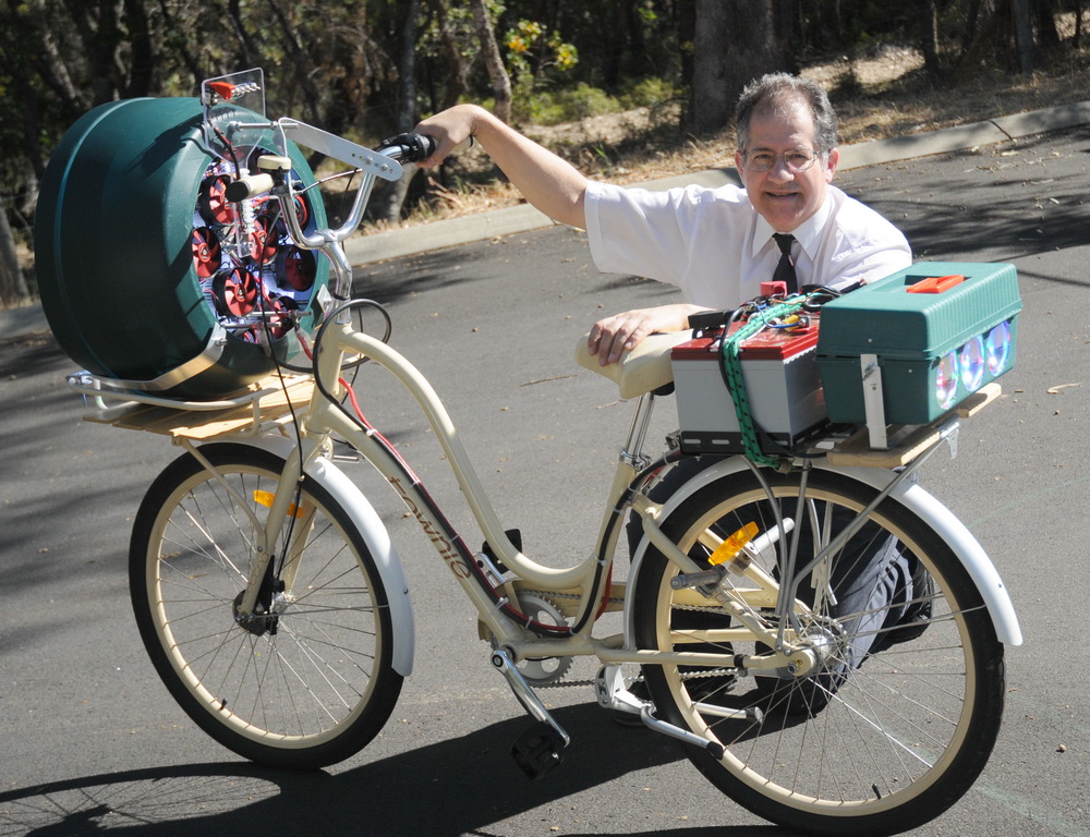
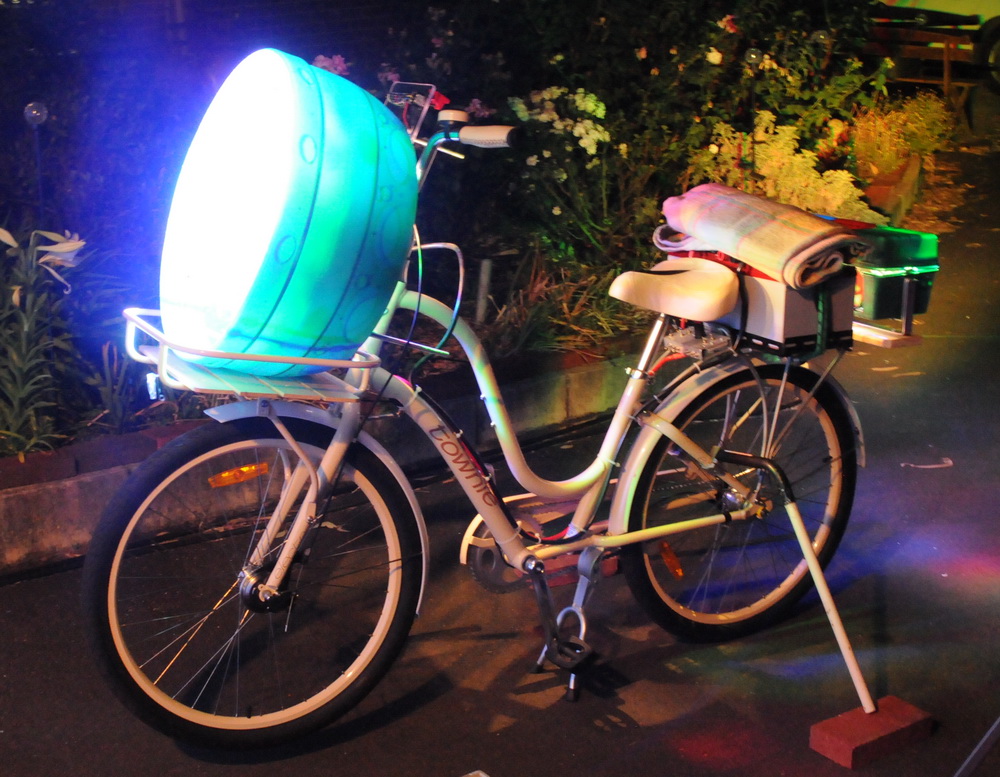
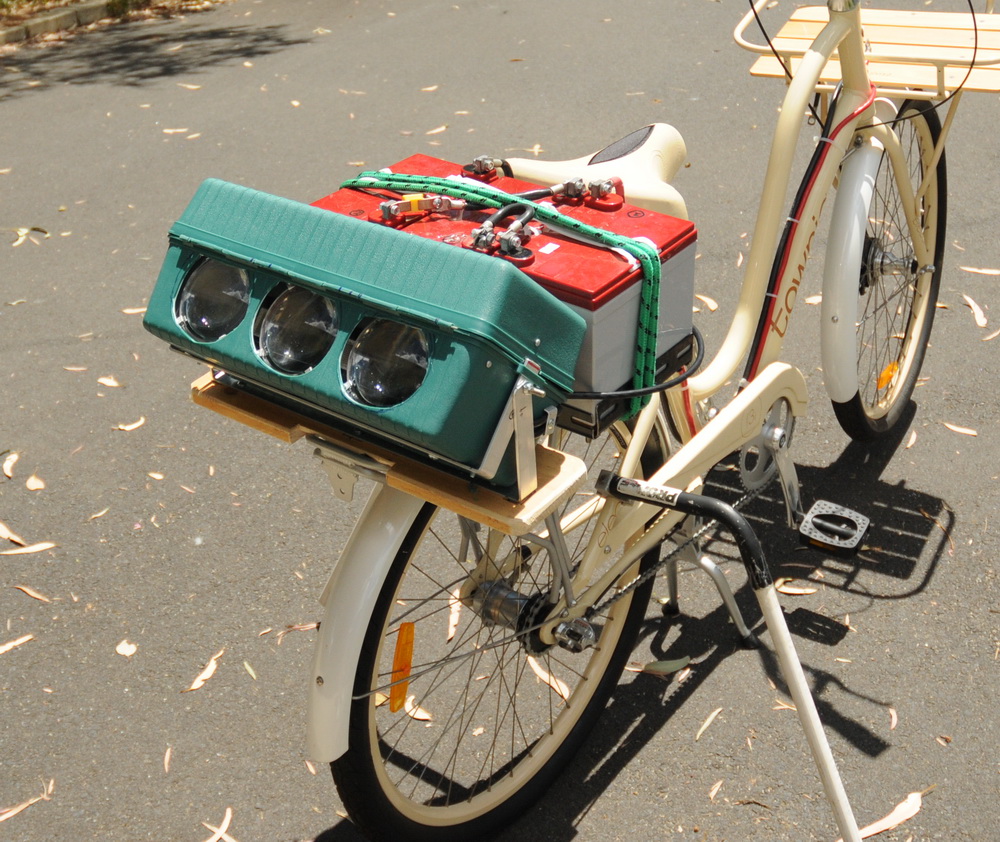
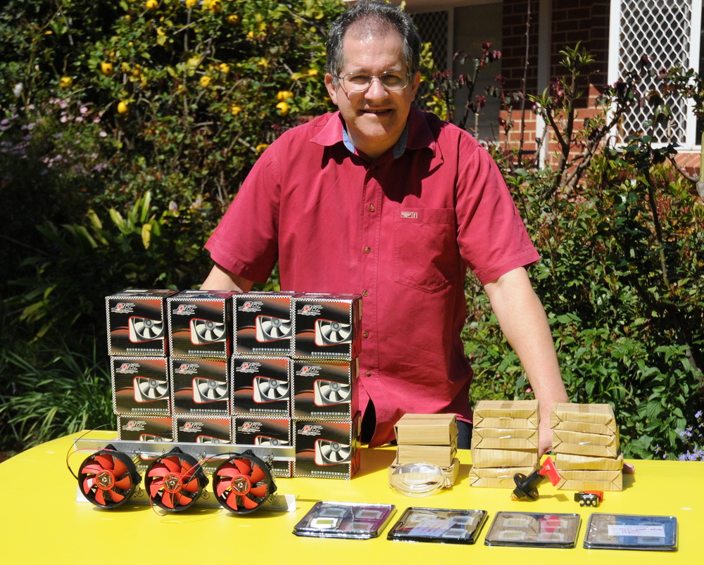
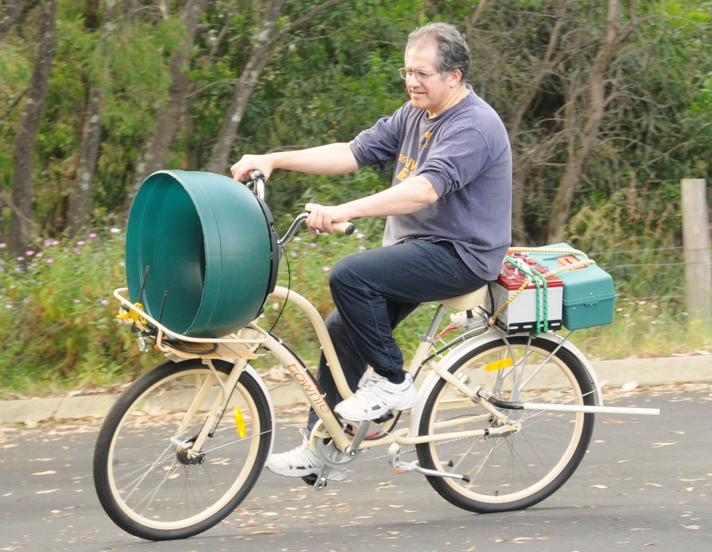
OK.Step one. Take a ladies bike with front tray and rear carrier. Add a big round thing in the front and some tacked on stuff and you can get some idea of where this is going.
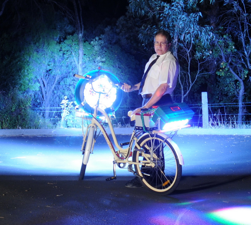
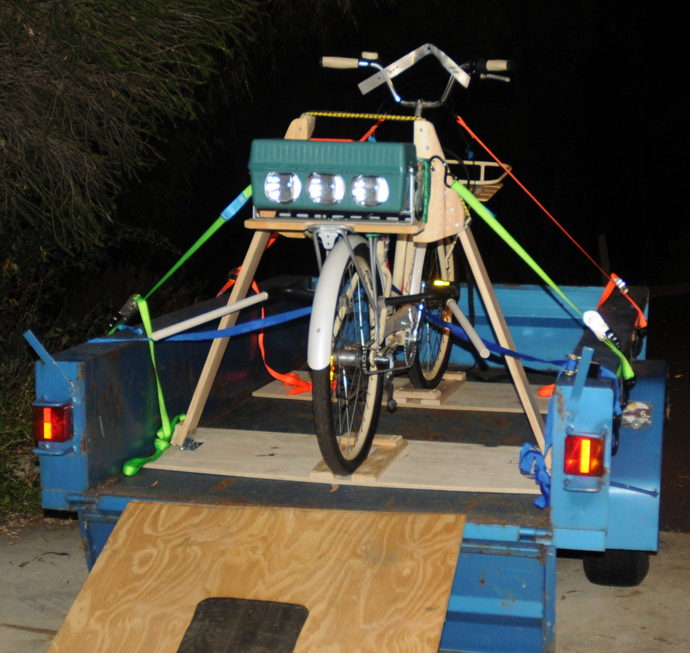
So here it is in its full glory.
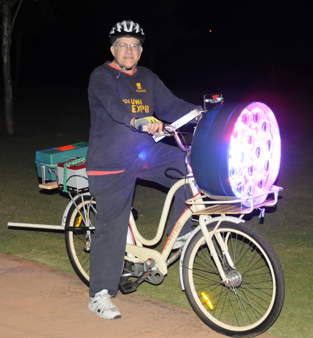
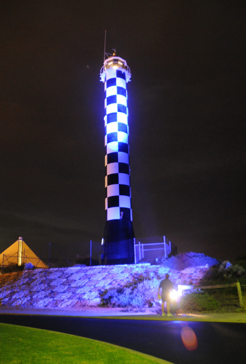
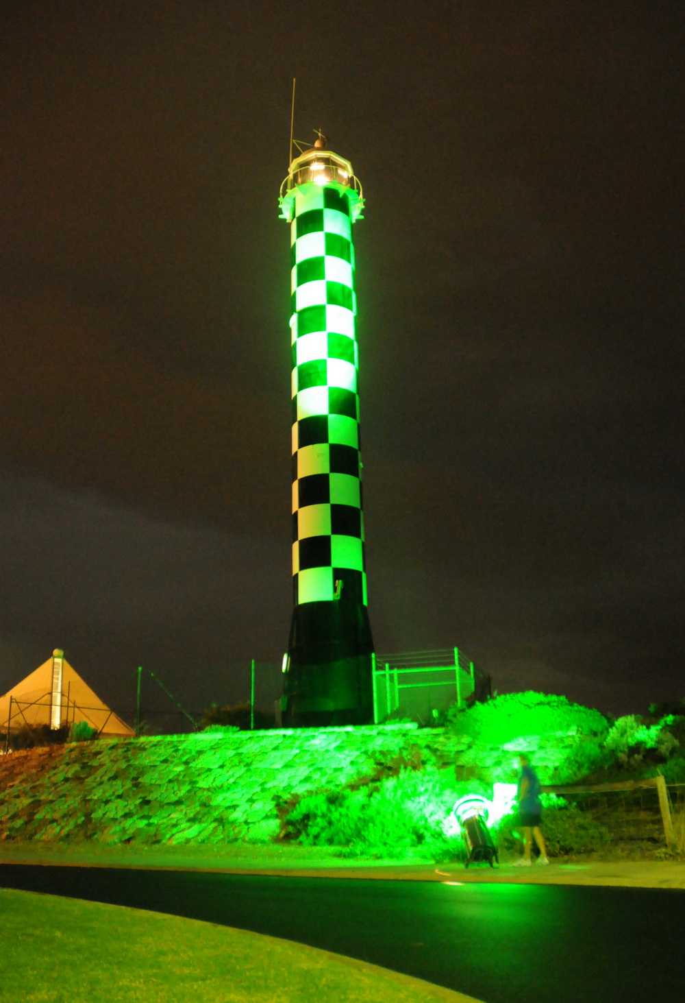
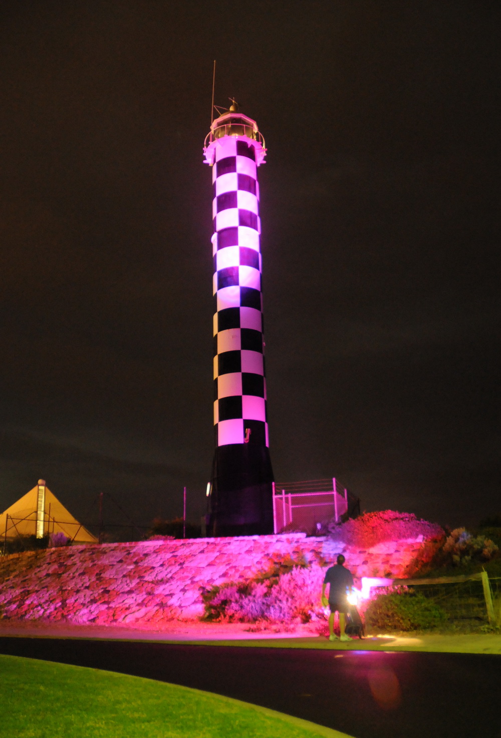
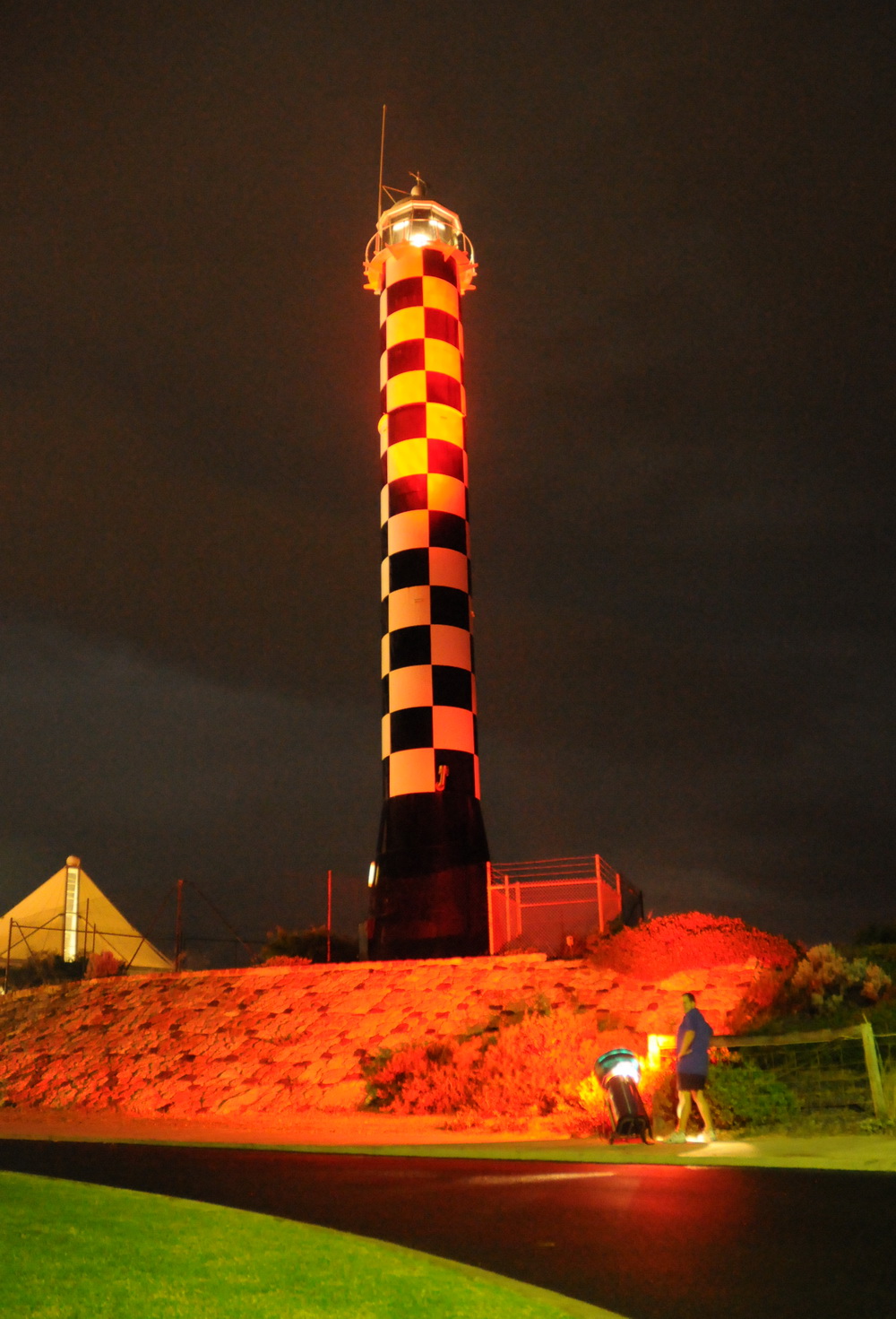
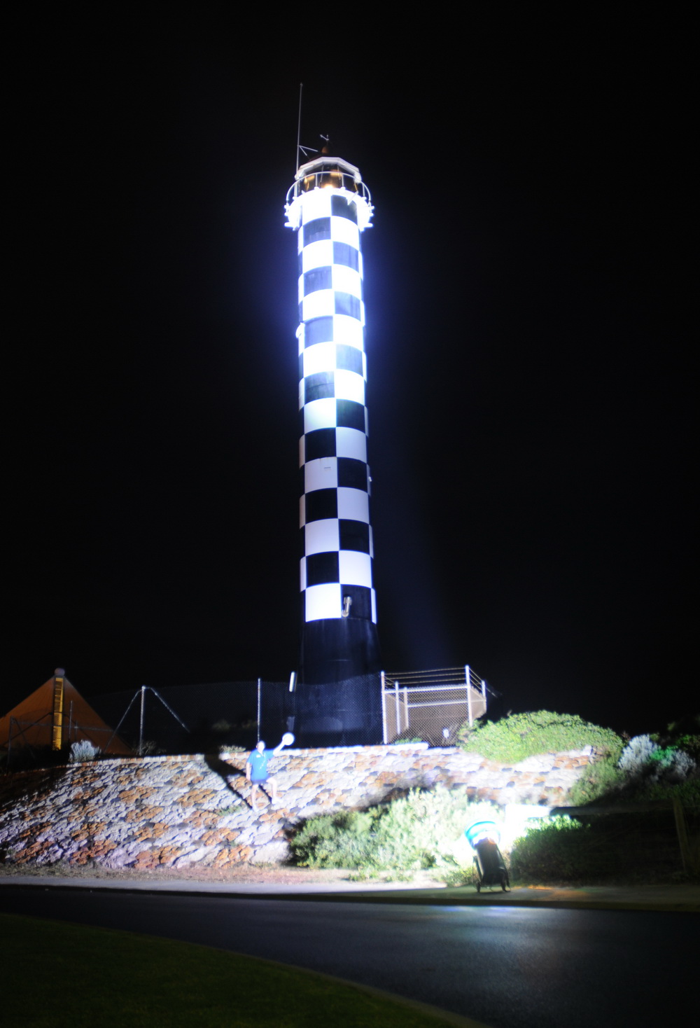
Lighting a lighthouse! Here is ONE 100 W 6000 lumen LED focussed to a 5 degree beam. I will be using 15 of these in the front of the bike. Check out my 100W LED page. The Bunbury lighthouse is on but you cant see it's beams easily in the photo from this angle. The 100W LED runs on three 1.3 AH, 12 V SLA batteries attached to the LED which is resting on on the wooden fence here. It is fan cooled and runs around 3 A 34 V via a 0.4 ohm resistor, if I recall. This is 6000 lumens - remember the 100,000 lumen total figure.
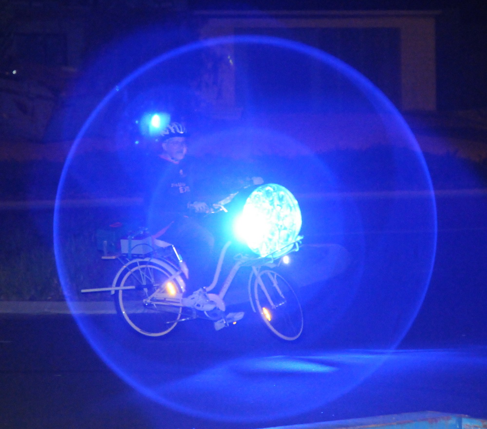
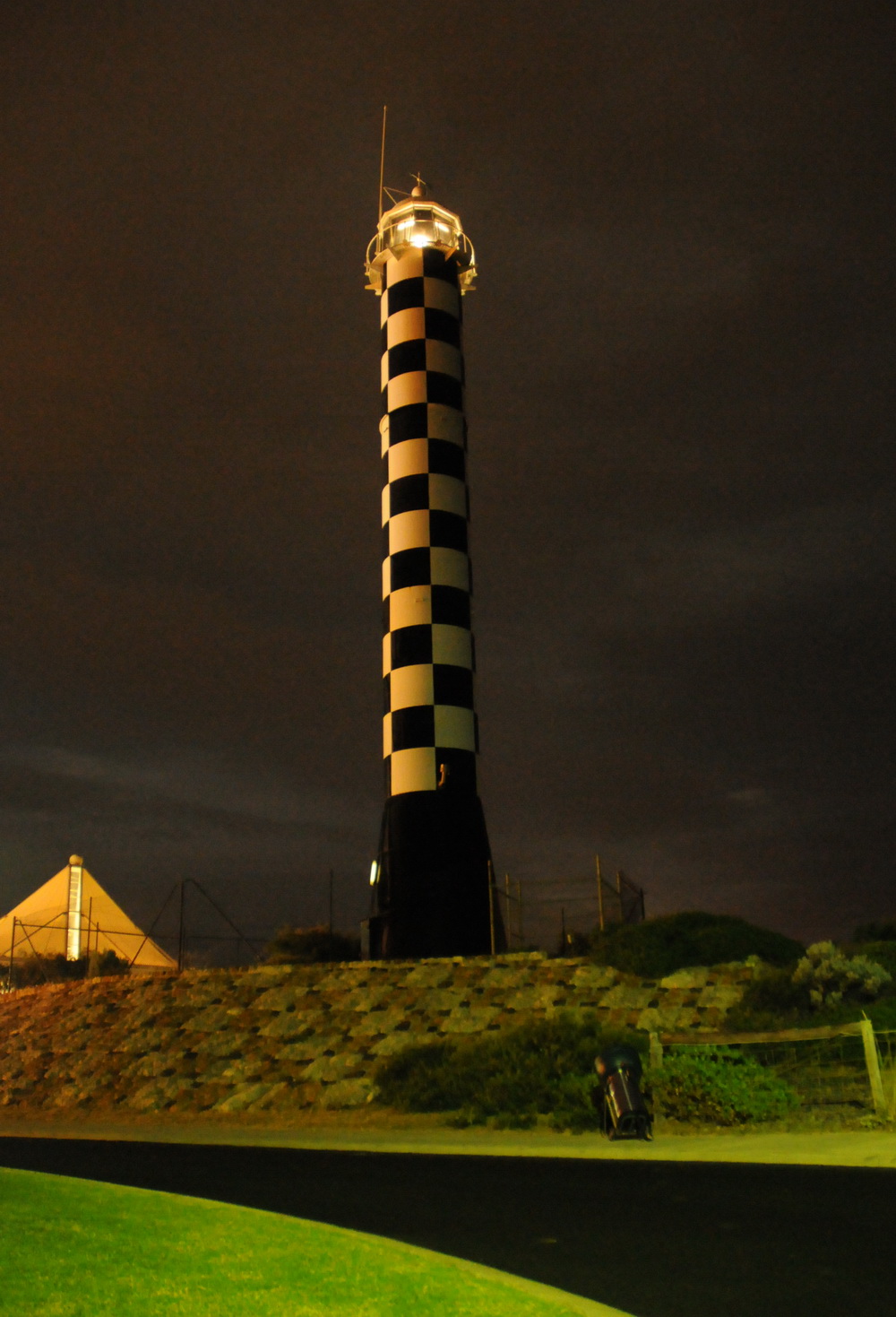
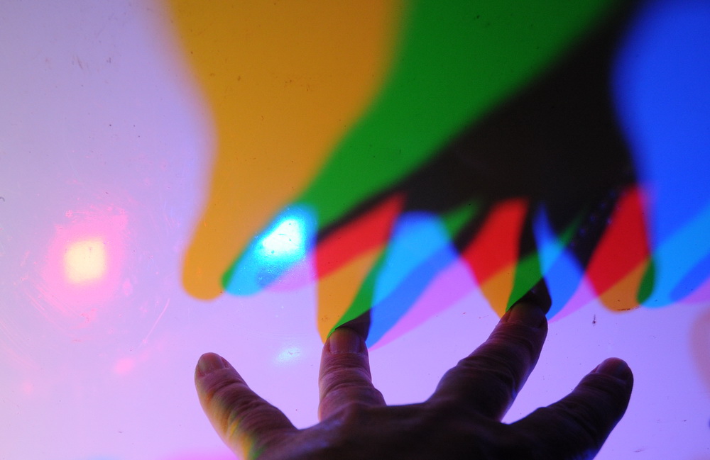
The World's brightest flashlight shown above lighting a lighthouse with different colours. The last photo is with lights on full with much shorter exposure. This uses 15 of the 100 W LEDs.
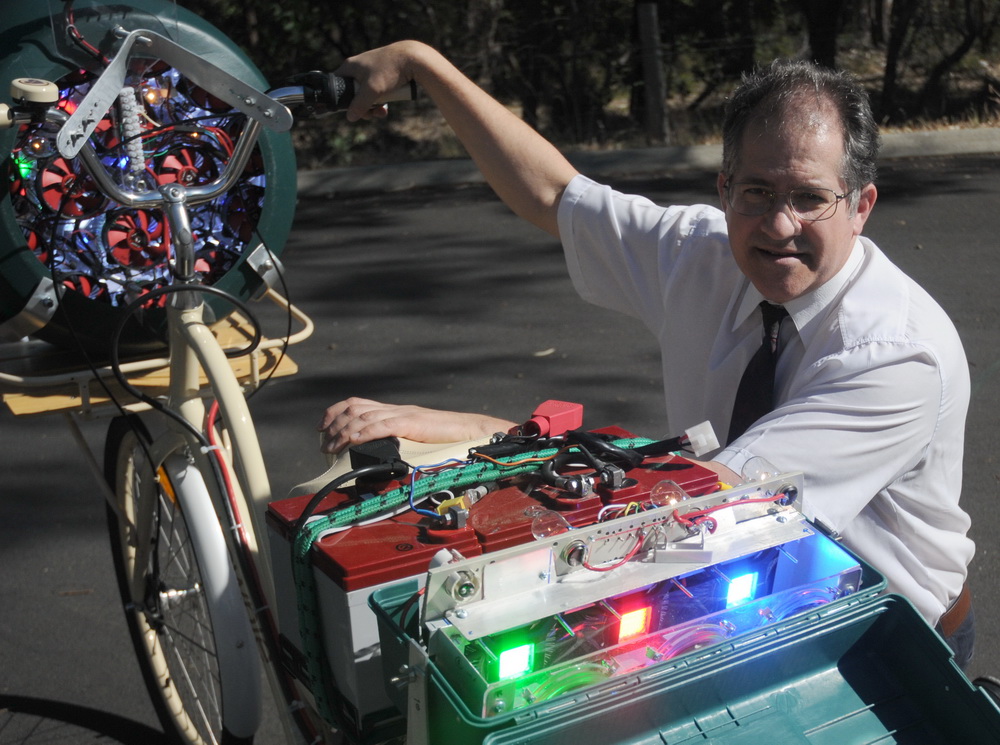
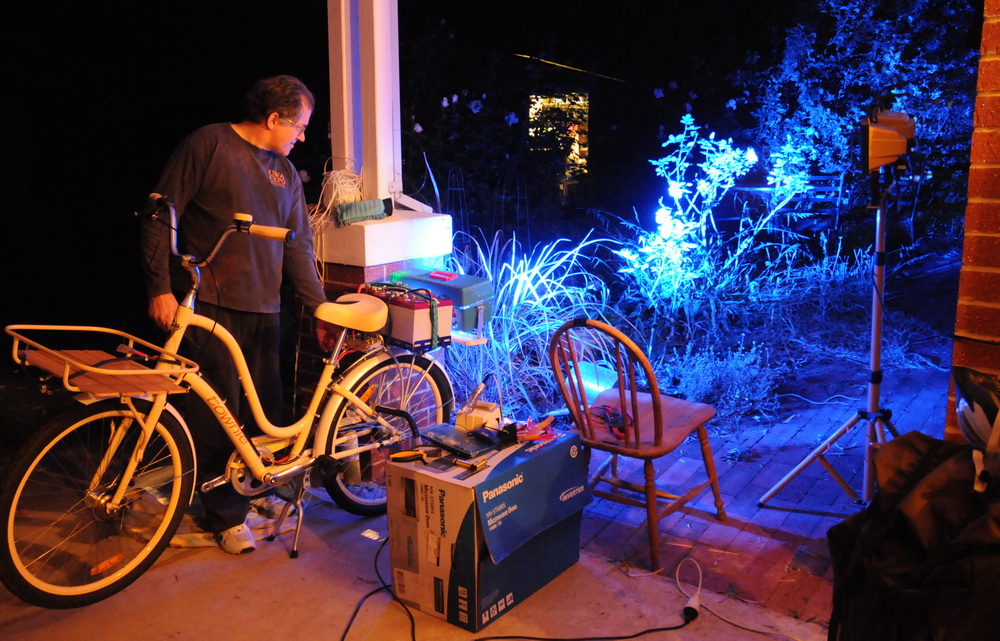
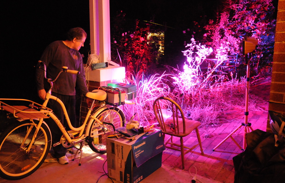
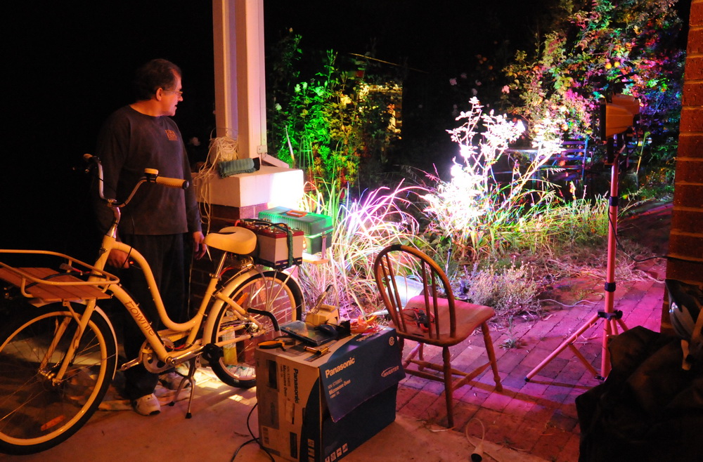
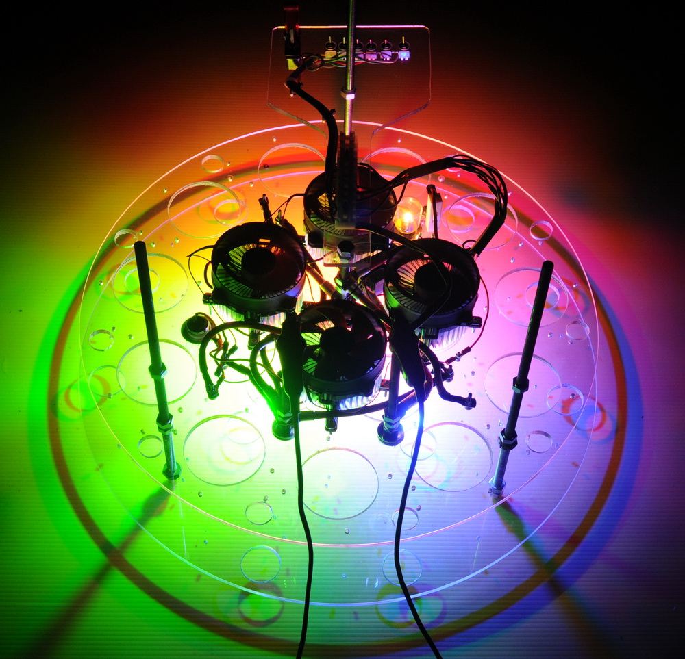
First light for the rear lights (above). These are separate red, blue and green and are mostly decorative at a "mere" 300 W. Shown here with blue (left), red plus blue (center) and red, blue and green (right).
Front lights:
LED data from
Led-world2007
are limited and to my mind insufficient and at variance with other similar
LEDs.
The lumen question marks in the tables below are for the quoted lumens from
similar LEDs from a different manufacturer which might be closer to the
true values.
100 W
Cold white
LED Parameter Min. Max. Unit Luminous Intensity 6000 6500 lm Color Temperature 9000 11000 K Forward Voltage 32.0 36.0 V Forward Current 3200 3800 mA
100 W
Red LED Luminous Intensity 6000 (? 3500) lm Wave Length 625 630 nm Forward Voltage 20.0 24.0 V Forward Current 4000 mA
100 W
Green LED Luminous Intensity 6000
(? 5000) lm Wave Length 520 530 nm Forward Voltage 30.0 36.0 V Forward Current 3200 mA
100 W
Blue LED Luminous Intensity 6000
(? 1200) lm Wave Length 460 470 nm Forward Voltage 30.0 36.0 V Forward Current 3200 mA
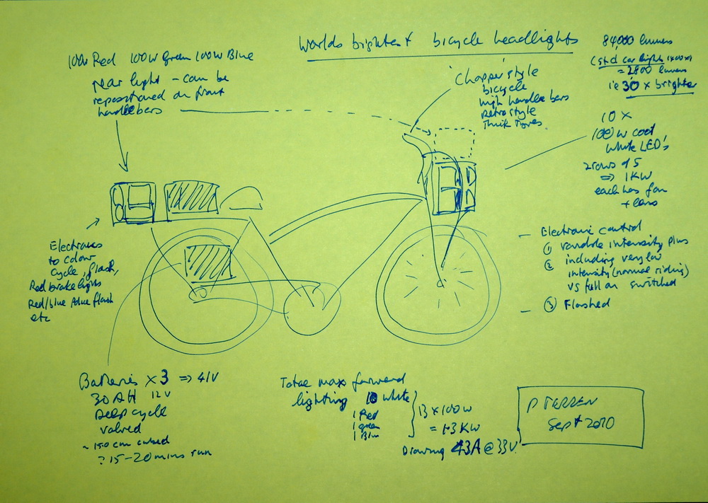
Concept
Some of my original concepts are shown above. Things have evolved a bit
since. "Ohh really .... someone else claiming the biggest and best".
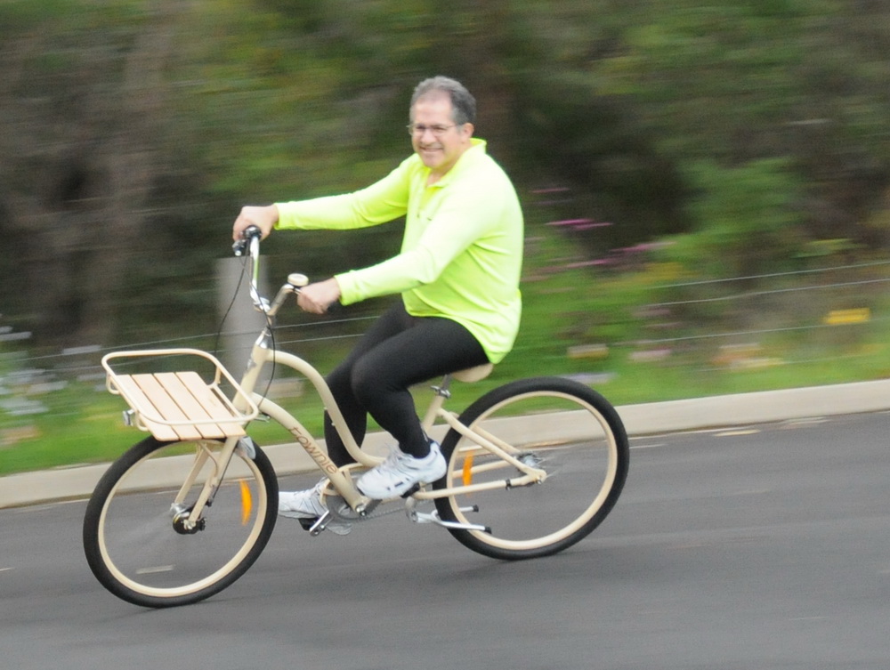
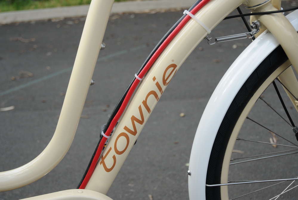
Bicycle: Electra, "Townie" ladies bike, cream AU$1300. Chosen by my wife. Ladies bike??? Big advantages of being able to step through and sit on the seat with feet flat on the ground to support the high center of gravity of the battery weight. The front tray is a big plus as well. No point in trying to make a heavily loaded racing bike or mountain bike I reckon. Old lady retro feel styling in cream. (I wanted the purple flowery one but my wife was firm). It has 3 internal hub gears and back pedal brakes. And it has a bell...
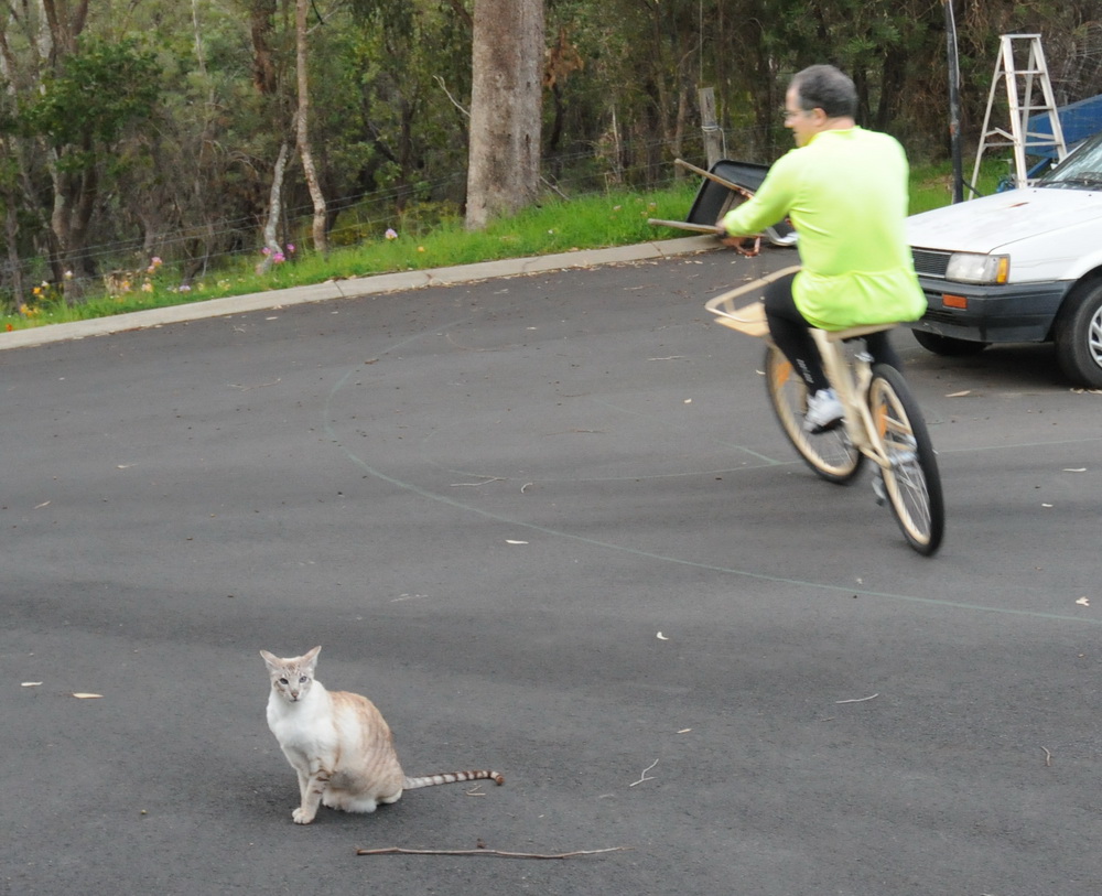
Our cat and it's WTF expression on first ride of the new bike. Cycle outfit is from my daily ride home on my "normal" bike.
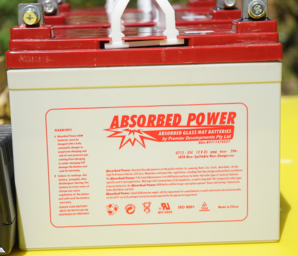
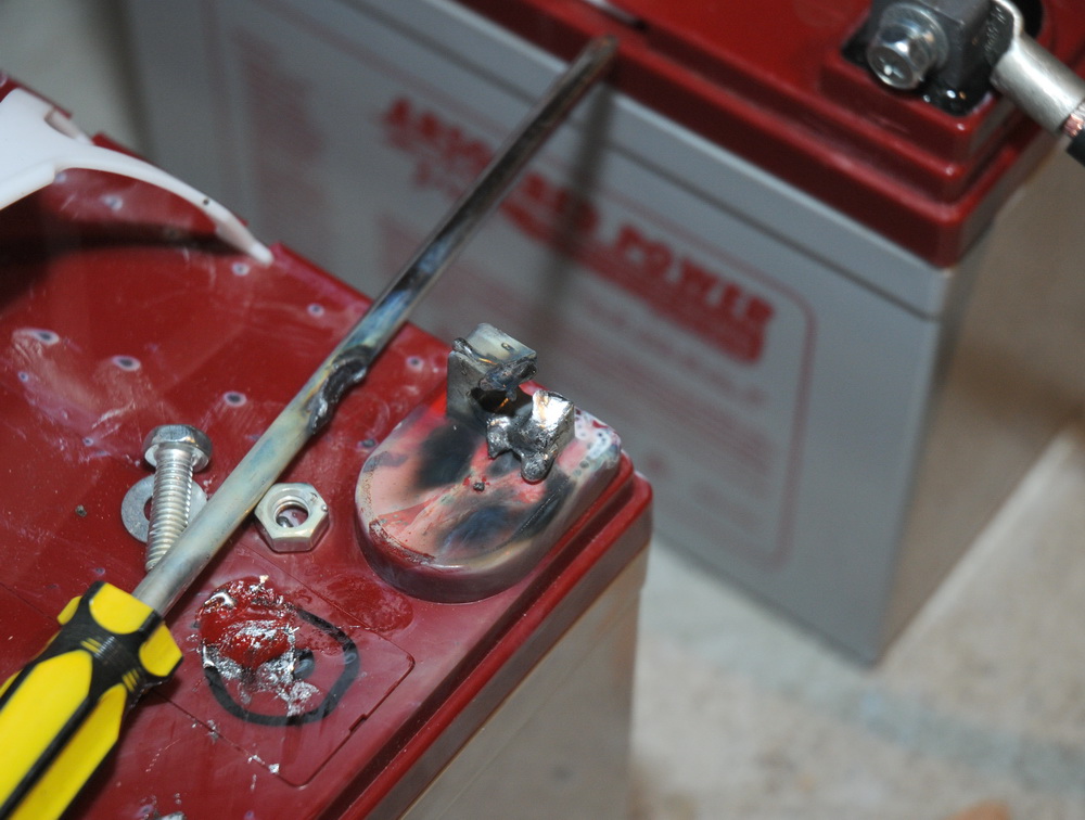
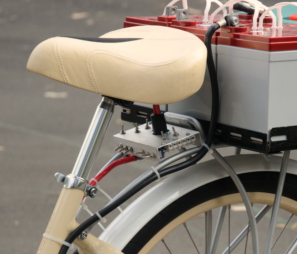
Batteries: Three 35 AH Absorbed Power deep cycle batts . These are like car batteries but with better construction to allow greater discharging. From the data sheet, these are good for 12.2 V 35 A dropping to 12.0 V at 12 mins. At 70 A, 11.8 V dropping to 11.7 A at 6 mins. Need 3 batteries to run 34 V at 52 A peak (1.8 kW) delivered to LEDs ie need to drop from (12.0 x 3=36) 36 V to 34 V. 2 V drop at 50 A is barely enough for heavy duty cabling and some big MOSFET's to do pulse width modulation (PWM). This is all a bit on the edge and will call for some tricks.
The left photo shows a battery close up, center photo shows shows what happens if you accidentally short circuit them while using a screwdriver to tighten a terminal and the right photo shows the three 2.7 A chargers.
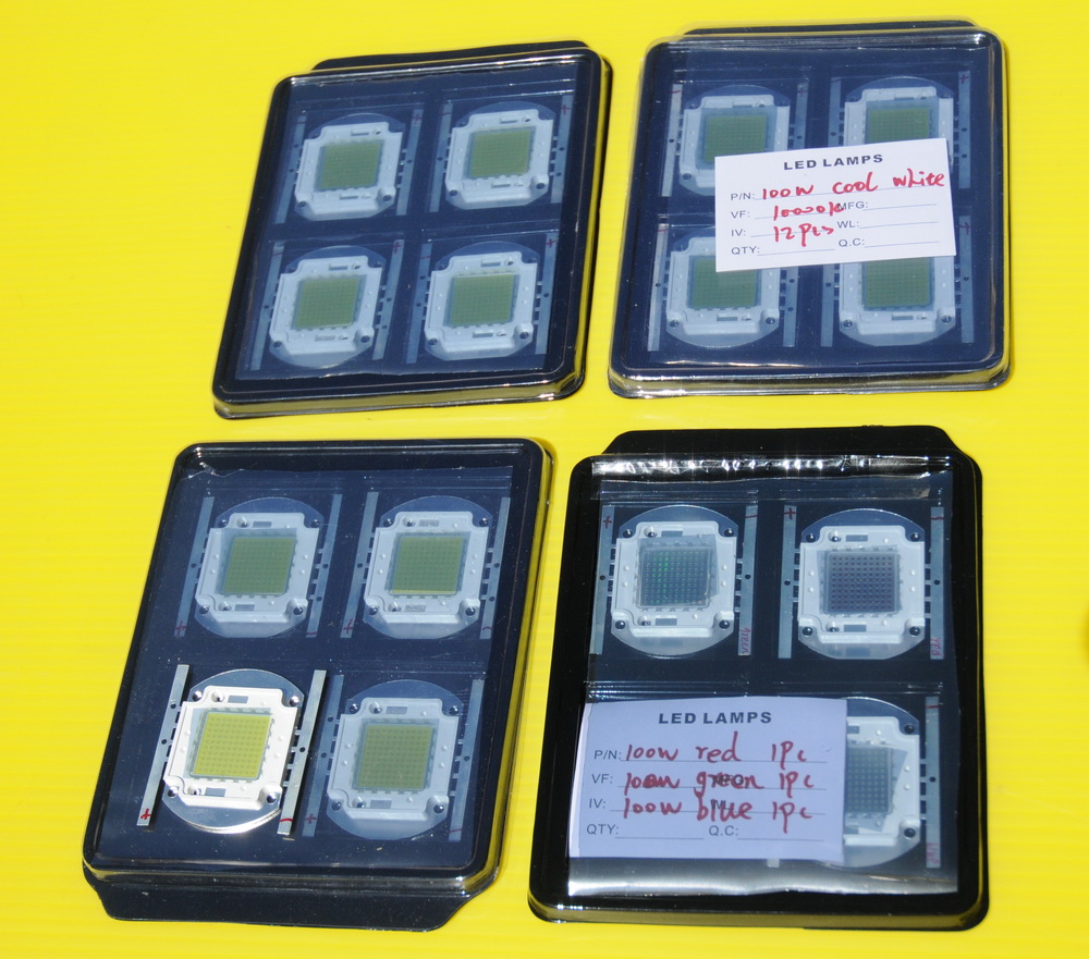
Front LEDs
My original plans were to use 11 x 100 W
LEDs.
Rated at around 34 V (32 - 36 V) at 3.5 A (3.2 - 3.8 A) with luminous intensity
6000 - 6500 lumens from a 1.8 cm x 1.8 cm surface. Roughly 10 Watt light
output by my calculations and hence have to lose the rest (90 - 110 W) as
heat hence the decent fans. These will be cold white 9000 - 10,000 K colour temp like those annoying expensive blue Xenon car headlights.
The LED ballasting is a complicated issue. LEDs are best driven by a
constant current driver since the voltage drop across them is fixed and any
attept to use a higher voltage will raise the total current dramatically. On
small LEDs a simple resistor is adequate but this is not really suitable
here.
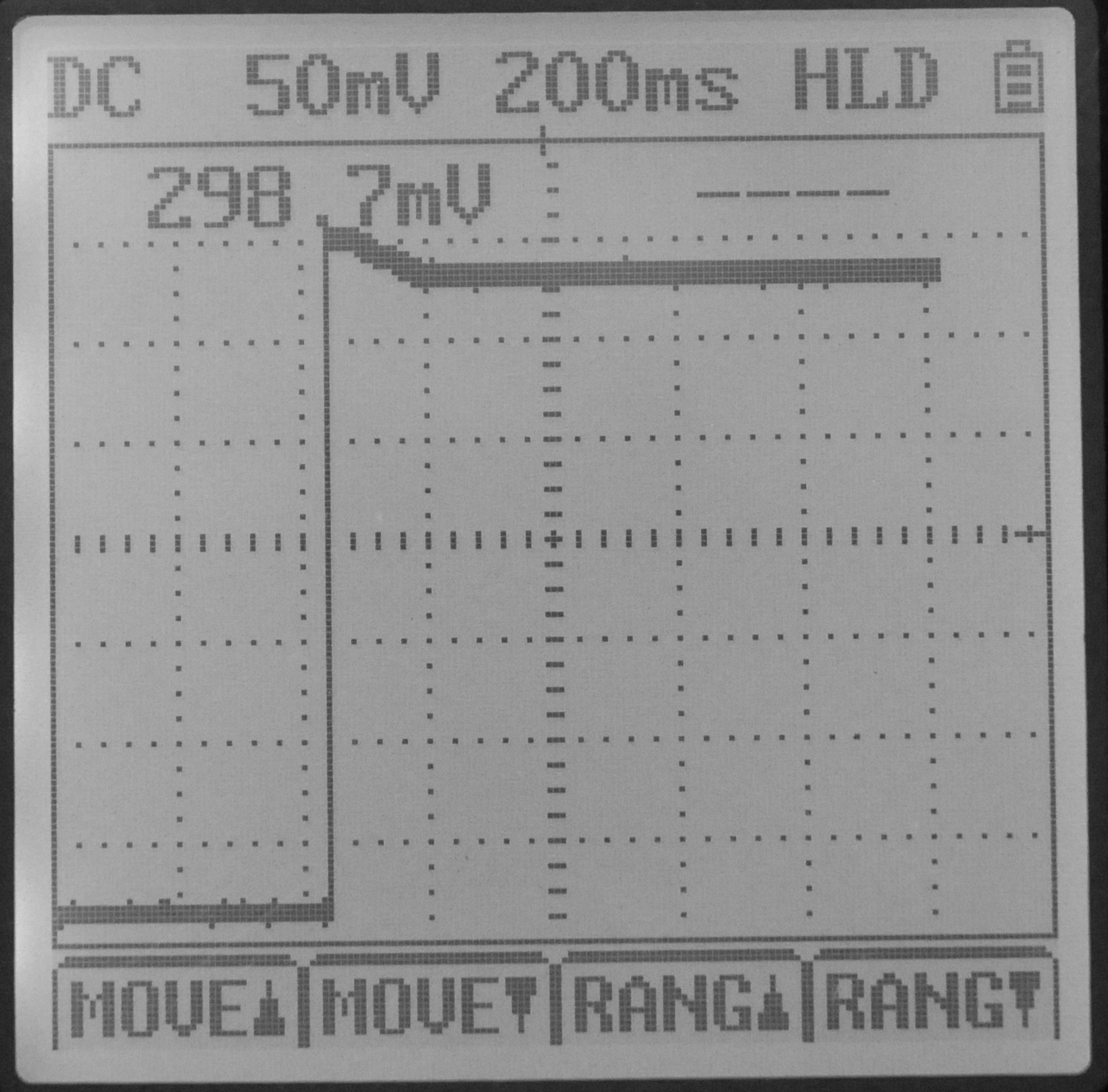
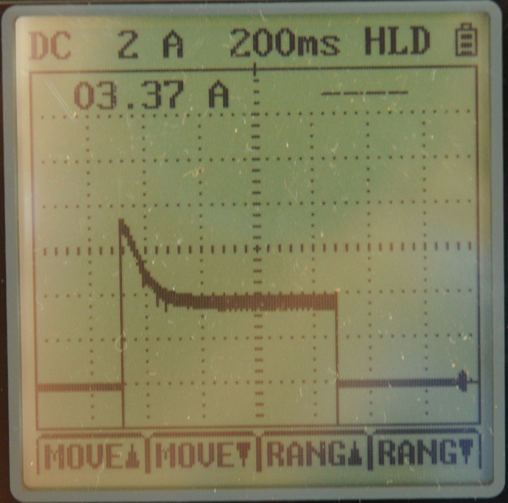
The left photo above shows the output of a photodetector taken at switch on of the white LEDs in the final array using a 6 V 18 W filament as ballast. Note the 5% increased light output at switch on which tails off in the first 100 ms or so as the light globe ballasts heat up. I had thought it might be greater. The right photo shows the current at switch on is almost 100% greater at 7 A reducing over the next 200 ms as the filament heats up. It suggests that I am running the LEDs (at least a single LED with a full battery charge), close to its maximum.
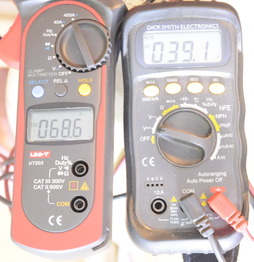
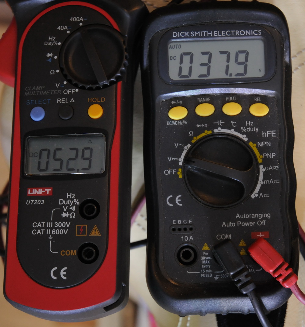
Here are the current and voltages at switch on of all 18 LEDs on the bike. Peak is 68.6 A (3.8 A per LED) which settles to 52.9 A (3 A per LED) 2.0 seconds later. Peak power is 2682 W settling to 2004 W.
The red LED uses both filaments of the 6V 18 W+18 W to drop 12 V, plus a 1.5 ohm 15 W resistor to drop a further 4 V, whereas the blue and green use one of the filaments only. I have a later option to switch in the second filament if the main voltage sags too much under load. Here is an alternative source for 100 W LEDs and specs. Snowdragon.
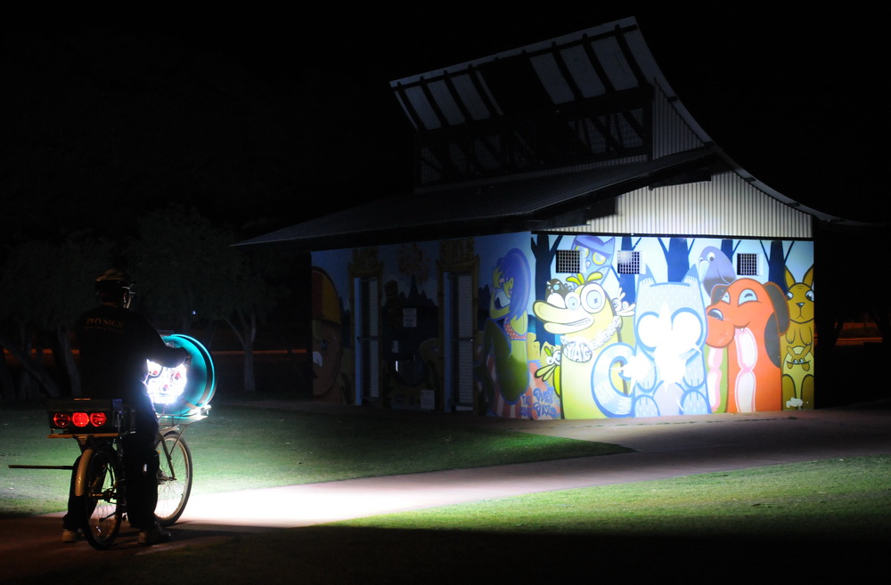
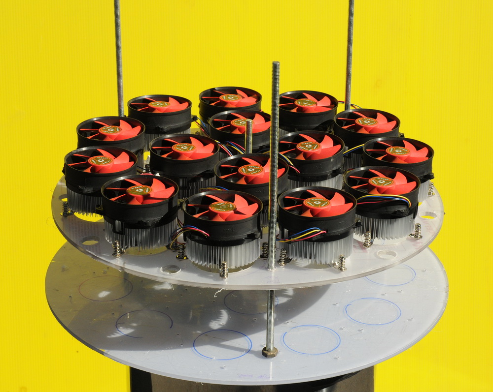
The left photo above shows me starting the front array construction, center photo shows how the fans will sit and the right photo shows first light of a single 100 W LED. Note the weak 150 + 150 W shed lights.
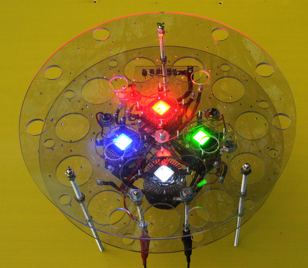
The left photo above shows the front array construction with red, green, blue and white LEDs at low power. Center photo shows the rear view with the rats-nest of wiring becoming evident, and the right photo shows first light of the partial front array on the bike. "Only" drawing 700 W at this stage out of target 2000 W.
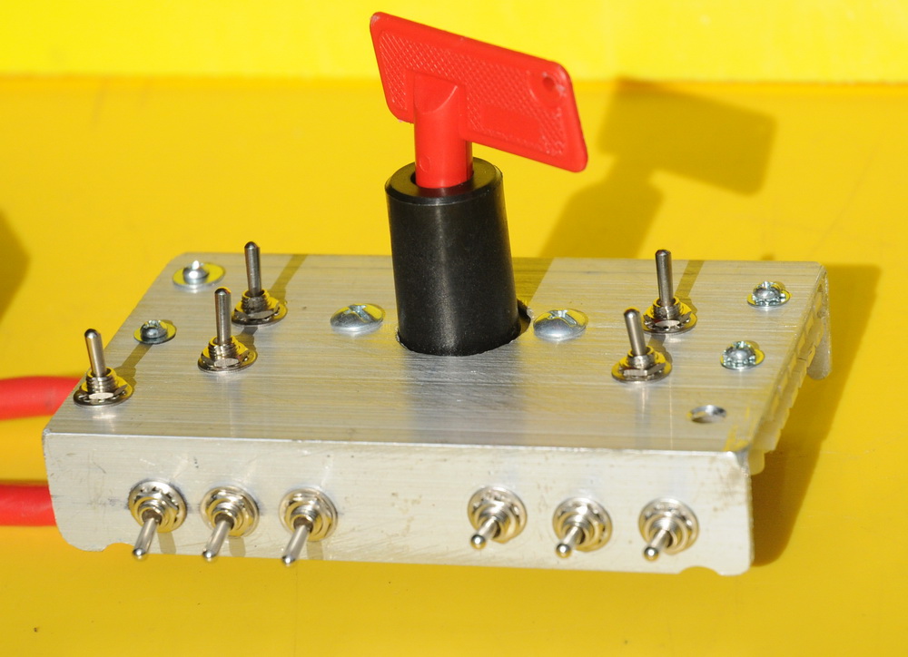
Controls
So far only RGB switching basic capability at present.
Rear LEDs
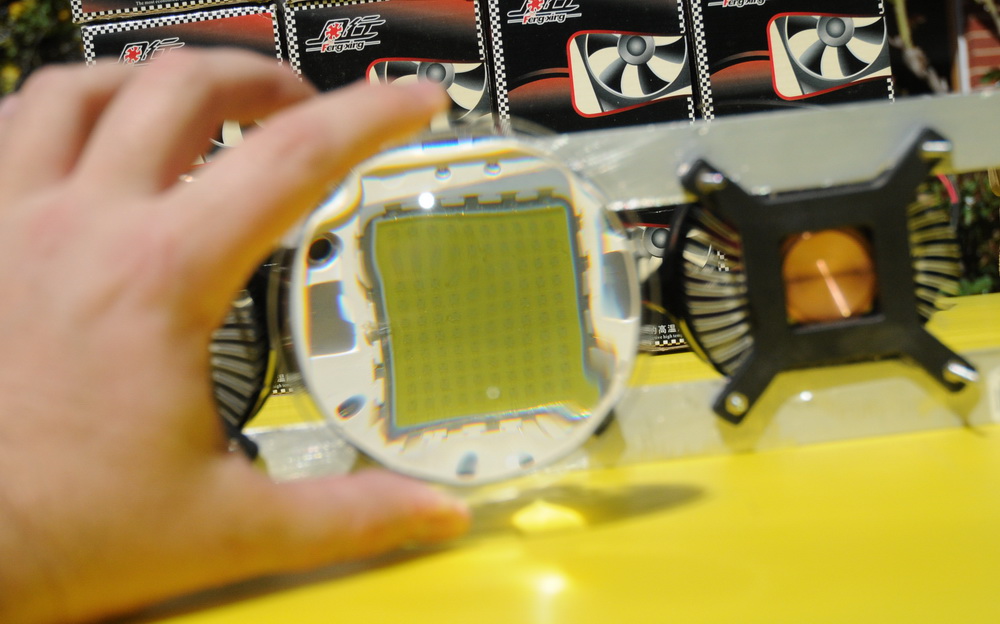
The red green and blue lights above left give really colourful shadows as the primary colors mix. The basic LED mounted onto the heatsink is shown center and the effect of the lens shows the fine detail of the 1W 10 x 10 array of LEDs on the right.
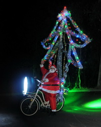
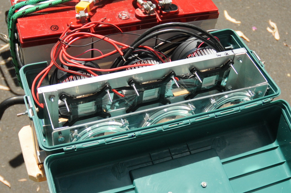
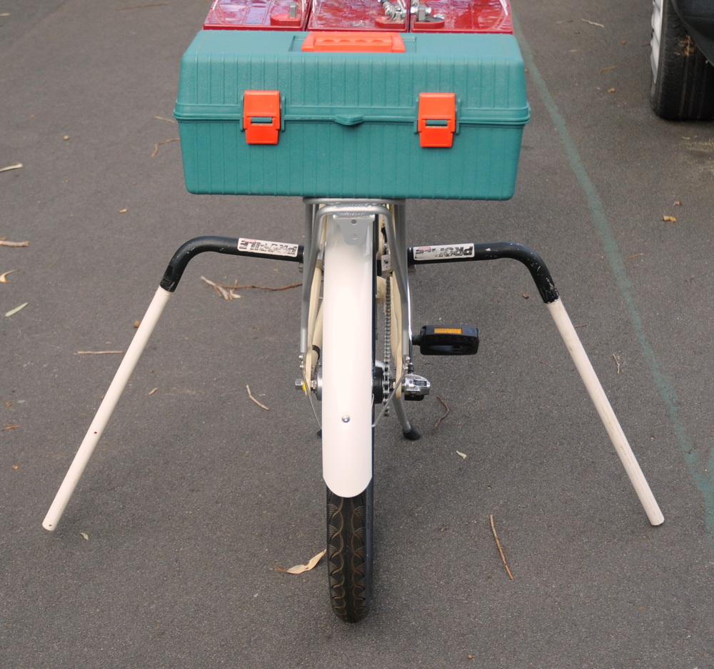
Above shows the mounted LEDs in the rear array which can be tilted vertically (for the Xmas tree project). The plastic toolbox is an excellent fit for the red, green and blue rear lights fans and optics. It is compact and I will be able to swivel it as well.
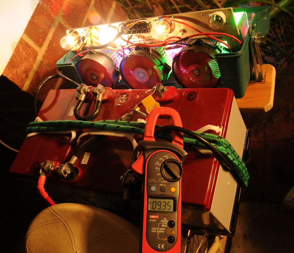
Above shows the as yet unwired rear array. The center photo shows current of 9.3 A 37 V = 344 W. Love this clamp meter with 40 A DC scale - bought it especially for this project. Ballasting of the Blue and Green LEDs is via 6V 18 W globes. The Red LED runs a lower voltage so has 6 V 18 + 18 W plus a 1.5 ohm, 15 W resistor in series.
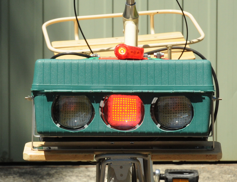
Above shows the low power (2 W) tail light riding mode with a normal tail light for comparison. Keeps it street legal (maybe). You can see each of the 1 W LEDs in the array. I also have a low power 10 W front light mode.
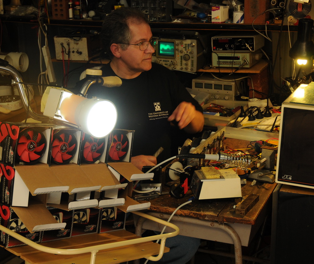
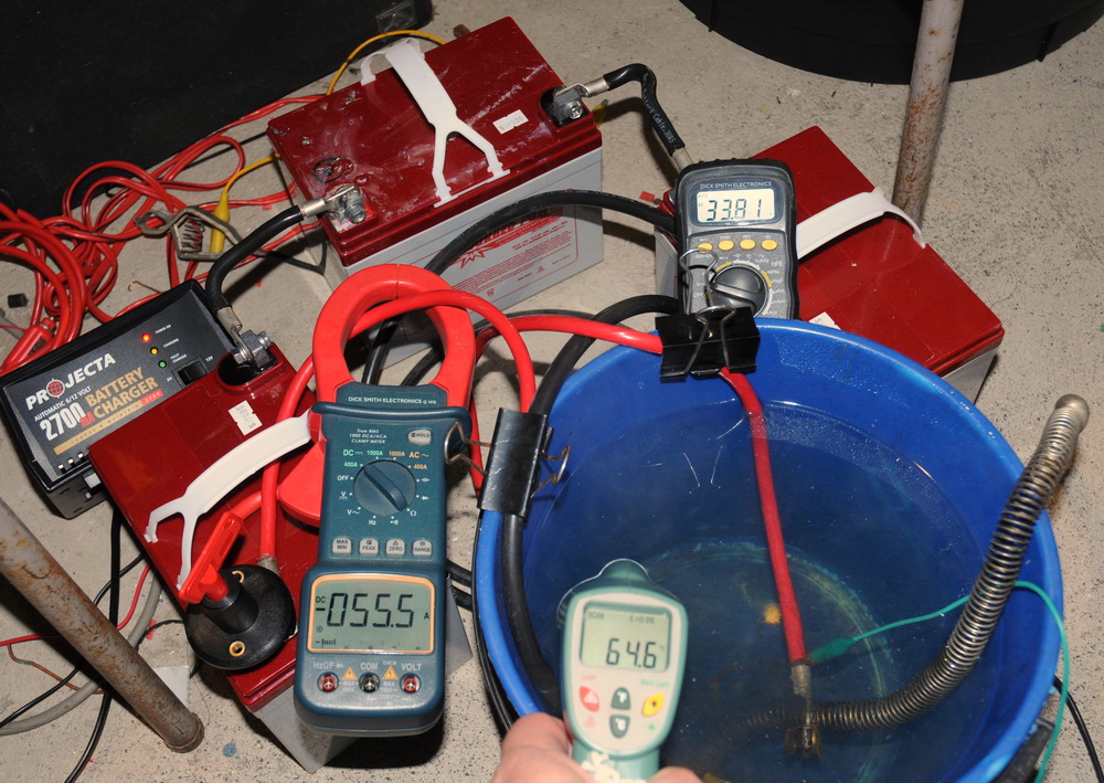
Electronics
Left photo above: Every man needs his shed... Right photo shows a battery power test. The meters above, read 55 A, 33 V and water coolant 65 degrees C during a power test. It took me a bit by surprise that the bucket of water reached almost 80 degrees C and I had to dash out to get more cooling water. That's what 1800 W does.
Heatsinks, Fans and Lenses
The 10 cm diam glass lenses need to be about 10 cm from the LED to focus to 10 degrees so you will lose some of the beam to side scatter. I want a tight 10 degree beam in front and a wider beam in the rear. Again from Led-world2007 . Later I hope to try a large fresnel lens to see if I can tighten the beam more.
Mechanical supports
I made an outrigger stand in the left photo, as the inbuilt one would not handle the 33 kg battery weight so high up. I cut up a tri-bar set that I got for a few dollars from a tip years ago. These are extensions to the handlebar of a road or mountain bike out forward for a better racing position for triathletes in particular. Add a PVC conduit and these can provide a good support and can be flipped backwards out of the way when the bike is being ridden. For trailer use a more solid setup was needed in the right photo. Reminds me of the pun: A bicycle can't stand on its own because it is "two tired".
Then I made a battery tray out of perforated angle iron
and particle board. Simple and effective but
quick. Downside is the centre of gravity is high but it is much more compact
and unobtrusive than some other ideas I had.
Also able to do the heavy cabling to the front of the
bike - needed as can't afford much voltage drop at all at 55 A+. Black cable
had 85 mV and red cable 235 mV including switch ie a total of 0.3 V at full
load.
It handles like a tank but is still rideable. But don't I look stylish riding it! Don't forget that this is a show bike and not really for much road use.
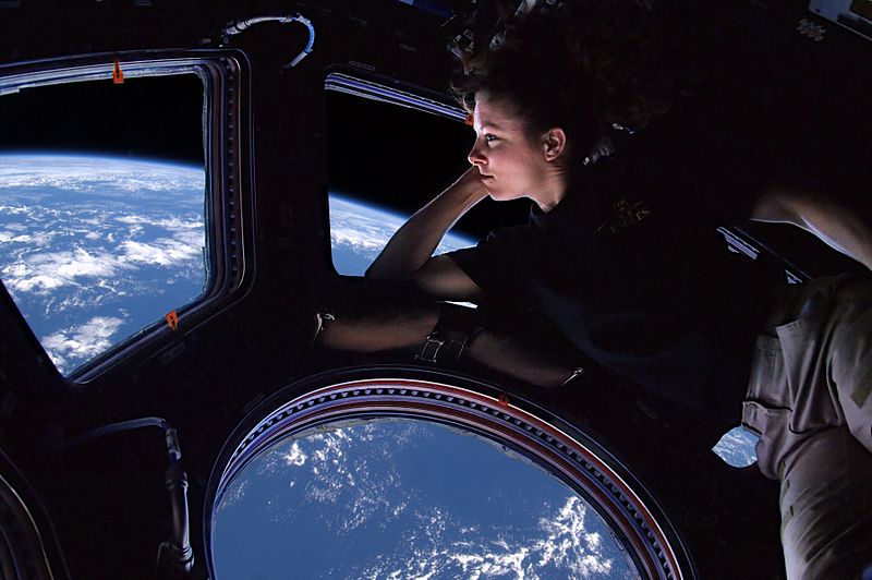
See it from space?
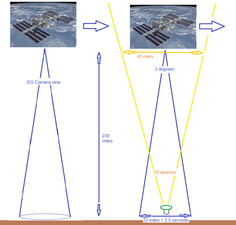
The ISS has a nice recently installed viewing
cupola (above left) where astronauts can take happy snaps like
Las Vegas
(above right). This has the reputation of being the world's brightest city
and the
brightest lights are probably beams facing upwards highlighting buildings like
casinos etc. Individual lights can easily be seen as well as yellow low
pressure sodium street light lighting the roads in the "suburbs".
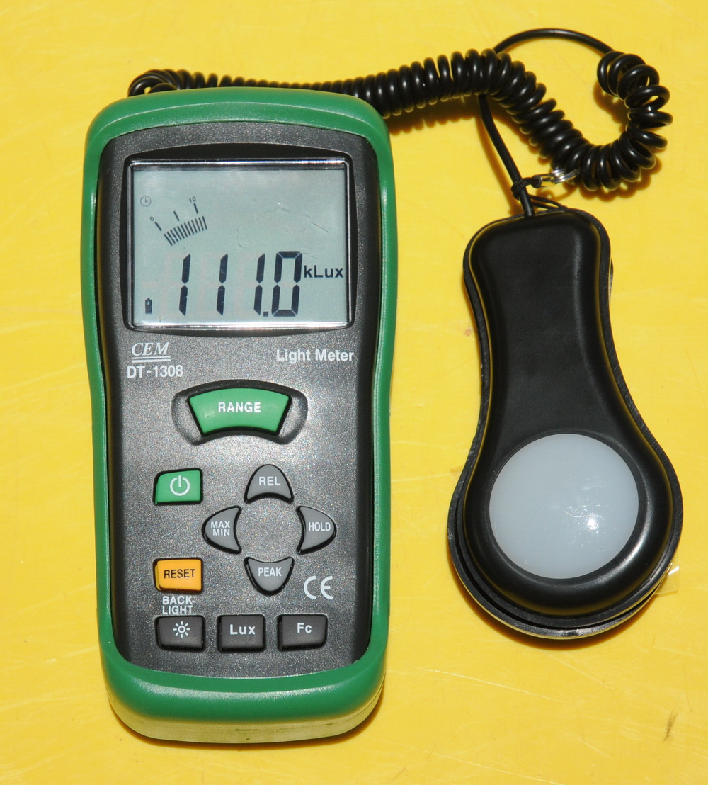
Now let's compare that with an actual measured reading using a lightmeter.
Above is the lightmeter recording 111,000 lux in afternoon sunlight. Meter
range is up to 400,000 lux. But how will you know it is my light when seen from space? Easy. Just modulate it on and off.
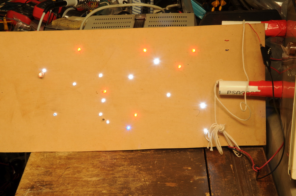
Above is a model
I made
with a lot of LEDs to demonstrate the concept. The still photo gives
no indication which is "my" light. The moving photo image, however, makes it
very obvious and shows a row of dashes as my light is turned on and off
electronically. In addition, the modulation can be smarter than simply on and
off. How about the world's first flashlight to satellite messaging
using Morse code?
Morse code is a largely obsolete messaging system using long "dashes"
and short
"dots". The best Morse code users are faster than SMS texting.
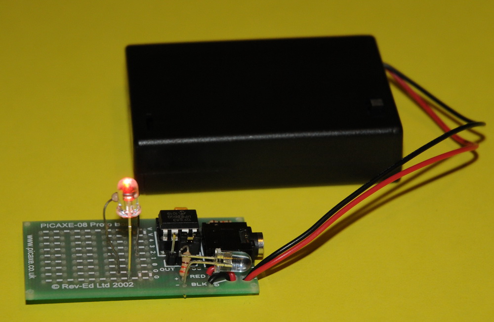
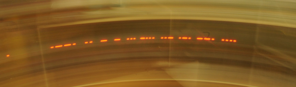
Above shows a PIC microcontroller programmed as a Morse code transmitter. It uses a PICAXE 08M and details are here.
Above shows the preprogrammed message "PITTSBURGH" named after a long running Morse beacon there. I have modified the program to give a 2 second delay then a dot then the message after a further 0.5 s. The Morse speed was doubled from the default of 10 WPM but needs to be faster. This is a 6 second exposure hence message is about 4 seconds. Needs to be a lot faster.
"TDU to ISS" in Morse dots and dashes would be: - -.. ..- - ---
.. ... ...
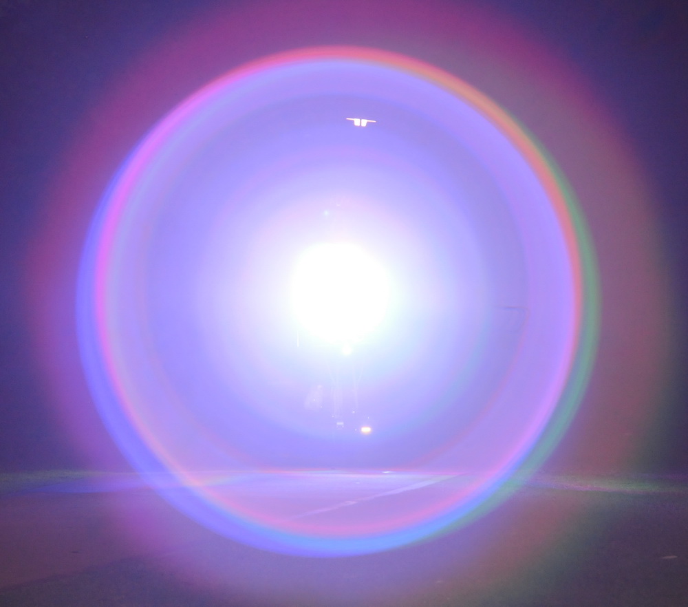
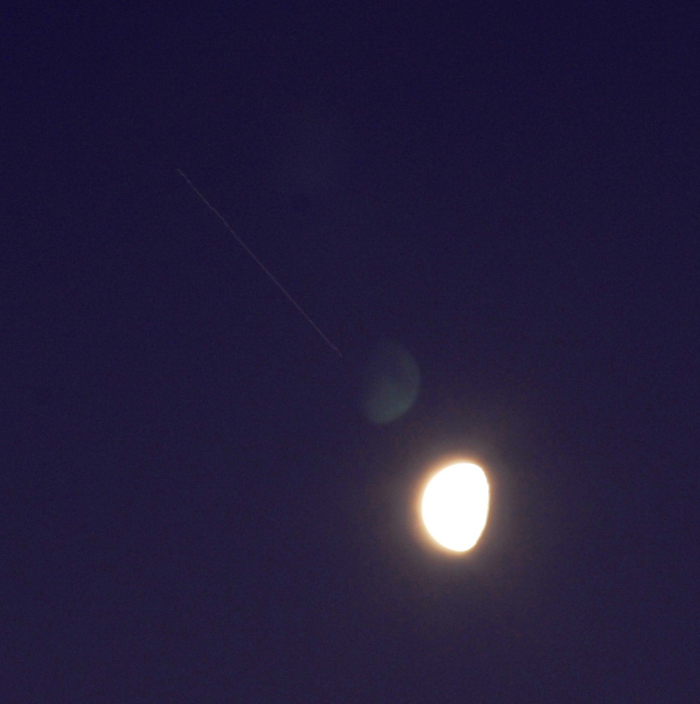
I took the above photo of the International Space
Station in a 4 second exposure on 4th March 09. The moon has a lens flare
and there is a lot of extra light from the moon and the time around sunset.
The ISS image passes about 3
moon diameters
(3 * 0.5 degree = 1.5 degrees) in 4 seconds although I didn't record the
elevation which was not immediately overhead. Apparent motion is from west
to east - opposite to the sun.
Note that if the ISS view is only 3 degrees wide, then there is no
requirement for my 10 degree beam to move at all. Interesting. However, that
assumes the ISS camera is aimed exactly vertically but this may not be
possible in what has usually been a handheld camera. In reality the camera would be pressed
up against
one of the cupola windows which would be unlikely to be at 90 degrees.
In fact they would have to aim it carefully to make sure the path includes
my position and they have only seconds to be sure. So I would be most likely
to get best results with tracking
it after all.
It will be easier for the ISS to have a wide field of view and for me to
have a narrower tracking beam. Just imagine that I am on the ISS. Would I be able to see the light or a streak with flashes of Morse code with a 400mm lens?
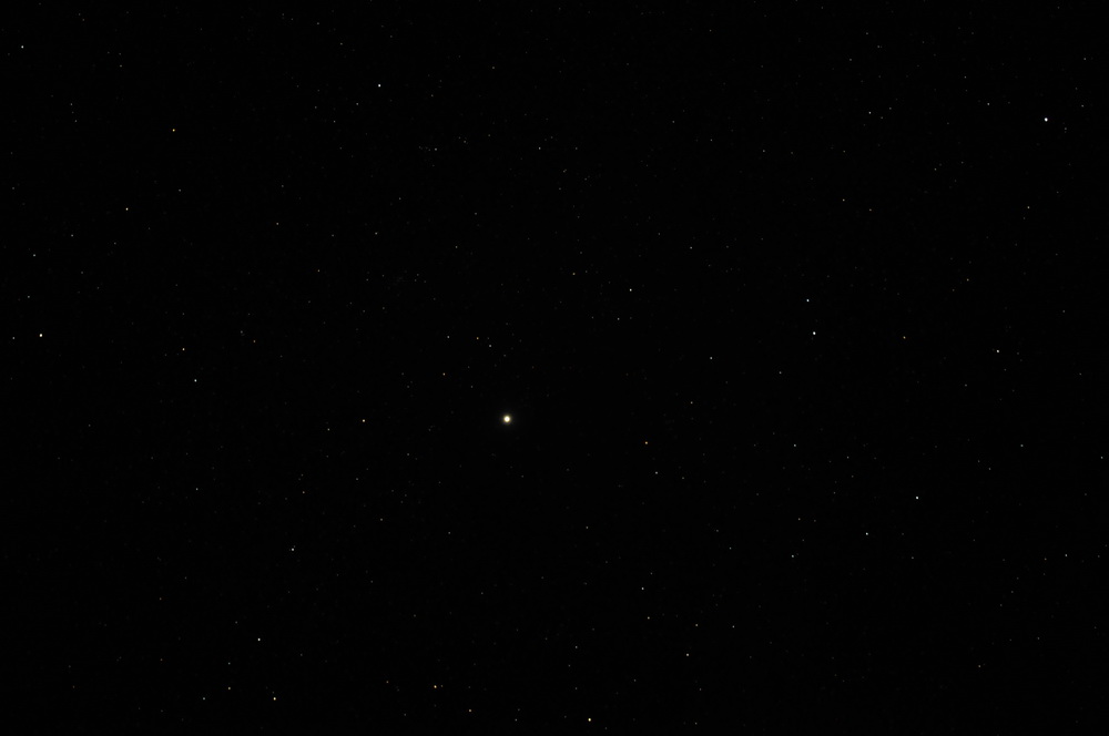
Here is Alpha Centauri which is one of the Pointers near the
Southern Cross
and the third brightest star at +0.01 apparent magnitude. The
left photo shows clear images of the star
(click to enlarge) and others with my 180mm lens and a Nikon D300 with a 5
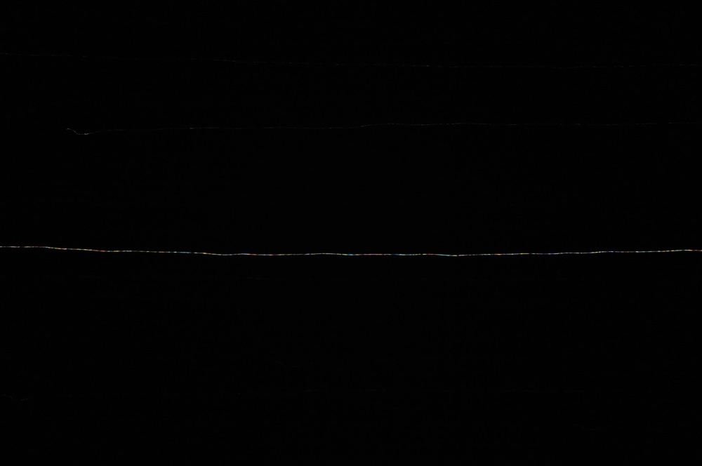
second exposure. The right photo
shows the streak of manually swinging the camera (faster than ISS transit
time). The star remains clearly visible although it has a lot of
"twinkle" as it was not that far off the horizon. It would be even better
with a 400mm lens and slower transit and the actual flashlight should be 0.7
magnitude brighter anyway than Alpha Centauri. So, yes, point the ISS camera in the right direction
and they will see it with magnitudes to spare provided the cupola is in the
right viewing orientation.
Also getting the "TDU to ISS" message across needs to be done twice in
2.5 seconds to ensure that at least one full sequence is received. That's
too fast for human generated Morse code so it will be electronically
generated with a small computer chip (PIC microcontroller) and ideally will
be seen in full across one picture of duration of just over 2.5 seconds. Where is the ISS? At 15 orbits per day, the ISS often comes close to my home town of Bunbury in Western Australia in any given 24 h even if not visible. Using NASA Skywatch, one can plot passover times and tracking data.
How can I be sure of the best ISS view. The brightest view will occur when
the ISS is immediately above and closest.
Realtime views on Google maps are here for example. If I travelled 125
km to Arthur River (33.396 S, 117.035 E) in dark rural countryside and faced
the light exactly vertically upwards on Jan 12, 2010 at 22:43:20 hours
(14:43:20 GMT) then the ISS would be directly above. I could flash it
a few times to say "Hi". Easy as that. But a combined Morse code and
prolonged visual contact with tracking would be better and have a
photographic proof of the contact. Note that I have to make sure this is
wake time for the astronauts which is 06:00 to 22:00 if I recall. They could
pop over to the cupola after lunch at 14:00 GMT.
But what could go wrong? Lots.
Overall this project seems viable and would likely generate some positive
publicity for the ISS (ahem.. and me). The simplicity of "seeing a
flashlight from space" is one that the public can understand.
Distance shots
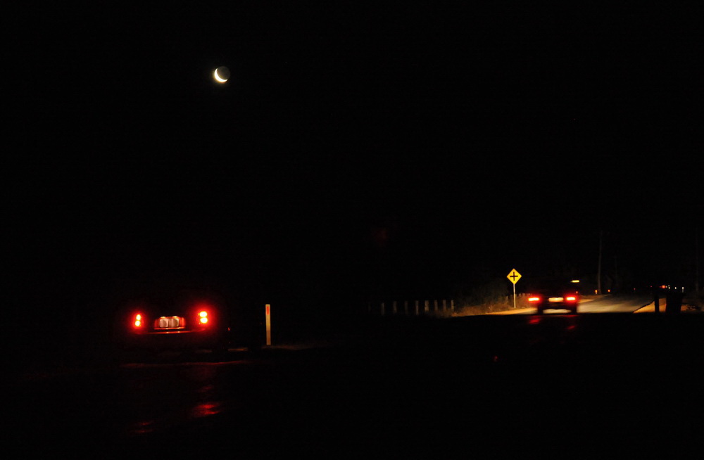
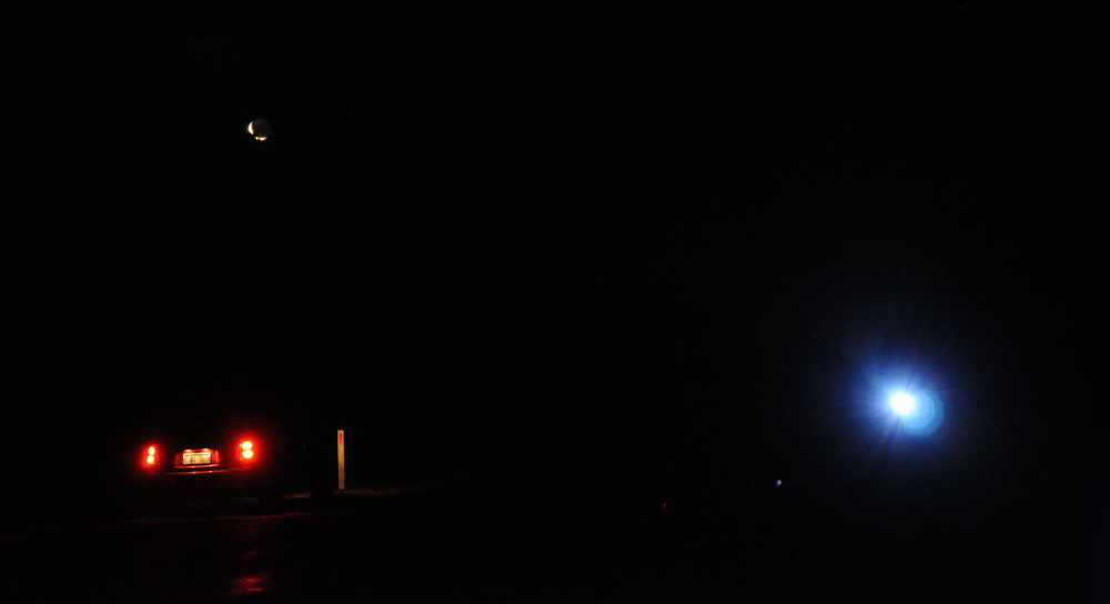
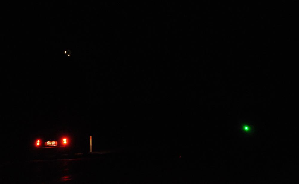
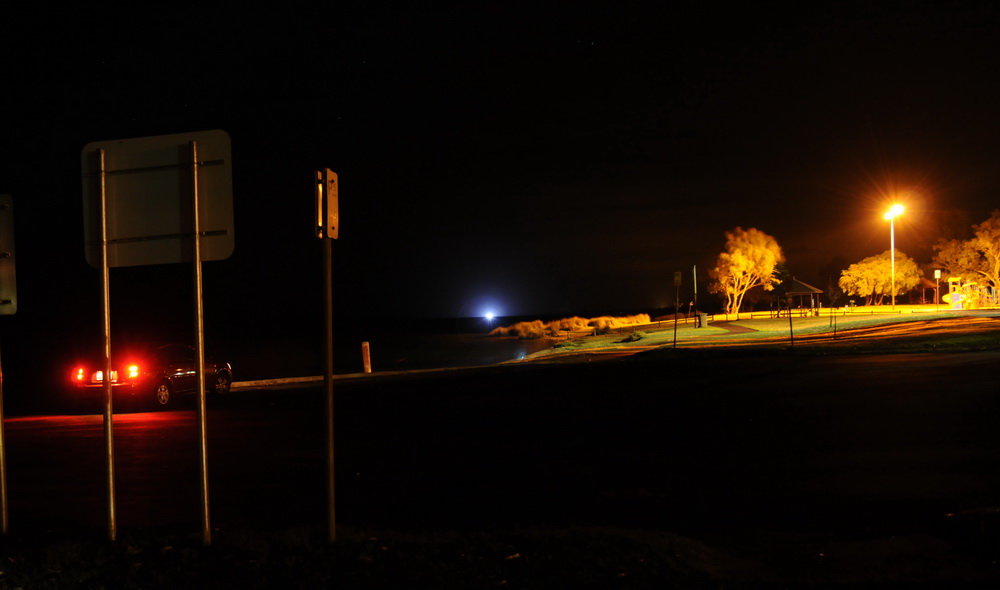
The three photos above are from my first distance shot. 2.5 km along the
straight stretch of
Lillydale Rd out of Bunbury. Here's the light seen from 9 km over a good part of the Australind Estuary (Bunbury, Western Australia).
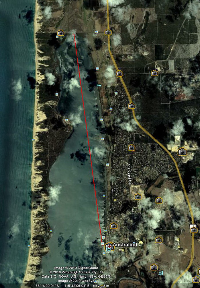
The left photo shows my light pointing towards the suburb of Australind across a long estuary. The center photo shows how the light appears from 9 km away with car taillights and streetlights for comparison. Beam width would be around 1.5 km. If shone at the ISS at 370km, the beam would be 1700 times less bright [(370/9)2 ] but with a dark field and dark adaption of the eyes this should be easily visible. The right photo shows the observation path from Google Earth. I also did a 12 km shot but got partially obscured by the geography.
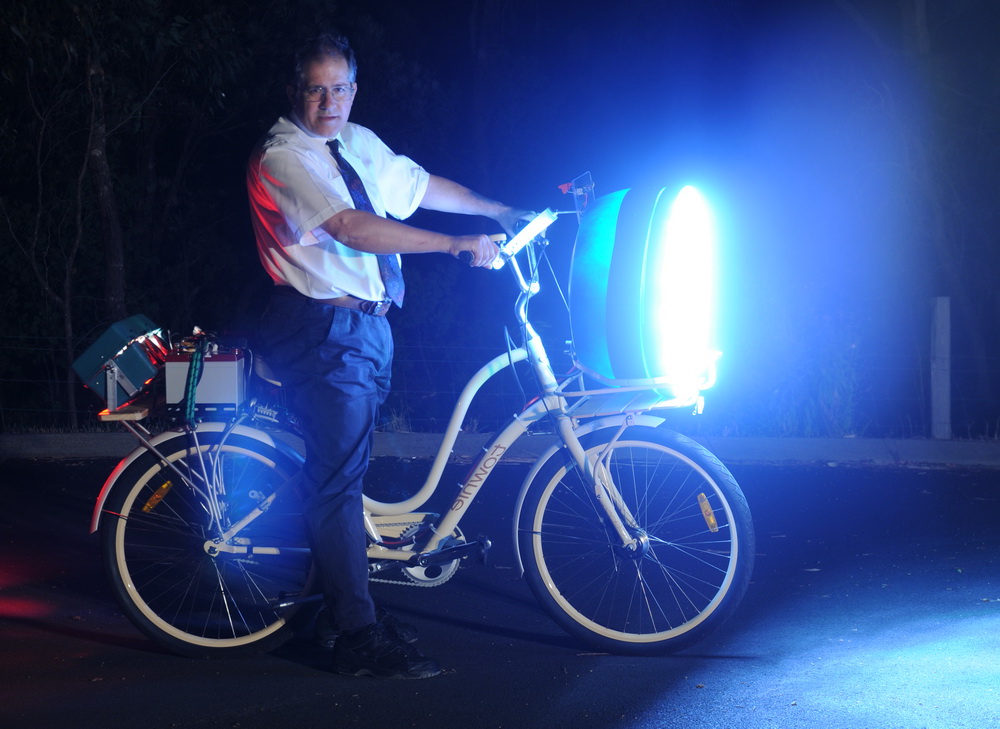
Media
The Bike and Xmas tree were covered by GWN regional TV on December 23rd 2010.
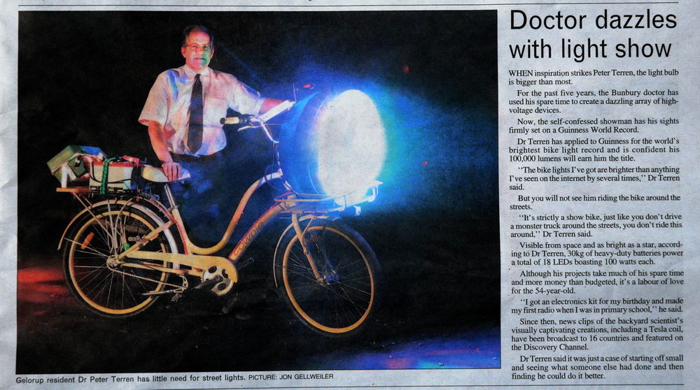
Video here The SouthWest Times did an article on 30th December 2010 for the World's Brightest Bike Light.
This news photo (left and center) is one of the only "photo shopped" images on my site. It was presumably done by the paper to remove the lens flare over my trouser area and to tighten the beam. Did I tell you I didn't like photoshop? The right photo is not retouched (apart from being flipped for comparison) and is one I took at a different time which looks very different. Two points. Firstly there is no "beam" in the real unretouched photo. A beam arises from the light through the air which is currently is dry, smog free and clear. Even a laser of medium power would be hard pressed to show a beam from the side, let alone a beam arising from outside the light source as on the left. So what is the bright haze? It is partly lens flare (with lens flare copy diametrically opposite over back wheel) plus the effect of light scattering from dust particles (largely diffraction) at low incident angle. The scattering should diminish evenly around a point source ie is typically circular. So which is the better photo of the front array lights? You judge.
Online newspaper articles in major papers of
Sydney Morning Herald
,
Brisbane Times and
The Age plus regional papers including
Areanews
Banyuleandnillumbikweekly
Barossaherald
Batemansbaypost
Baysidebulletin
Bendigo Advertiser
Bombalatimes
Boorowanewsonline
Bordermail
Braidwoodtimes
Busseltonmail
Camdencourier
caseyweeklyberwick Centraladvocate
Centralwesterndaily
Thecityweekly
Coastaltimes
Cobarage
Colypointobserver
Coomaexpress
Cootamundraherald
The Courier
Crookwellgazette
Dailyadvertiser
Greaterdandenongweekly
Devonporttimes
Donnybrookmail Esperanceexpress
Eyretribune
Farmonline Theflindersnews
Forbesadvocate
Frankston Weekly
Greatlakesadvocate
Goulburnpost
Gloucesteradvocate
Hepburnadvocate
Humeweekly
Illawarramercury Theislanderonline
Islandofcontrast
Knoxweekly
Lakesmail
Latrobevalleyexpress
Lithgowmercury
Macarthuradvertiser
Macedonrangesweekly
Macleayargus
Manningrivertimes
Margaretrivermail
Maribyrnongweekly
Meandervalleynews
Melbourneweeklyportphillip
Melbournetimesweekly
Melbourneweeklyeastern
Melbourneweekly
Meltonweekly
Merimbulanewsonline
Monashweekly
Mudgeeguardian
Murrayvalleystandard
Muswellbrookchronicle
Myallcoastnota
Nambuccaguardian
Narrominenewsonline
Northernargus
Northernmidlandsnews
Thenortherntimes
Northernweekly
Northweststar Nynganobserver
Oberonreview
Penrithstar
Portlincolntimes
Portpirierecorder Portstephensexaminer Queanbeyanage
RHSGnews
Theridgenews
Riverinaleader
Roxbydownssun Sconeadvocate
Southernweekly
Southwestadvertiser
Sunraysiadaily Summitsun
Tastamartimes
Tenterfieldstar
Townandcountrymagazine Transcontinental
Ulladullatimes
Victorharbortimes
Waginargus WAtoday
Wellingtontimes
Whyallanewsonline
WimmeraMailtimes
Westernherald
Winghamchronicle
Wollondillyadvertiser and the West. There was a radio interview with 4BC Queensland Australia on December 26th 2010 as well.
World's Brightest Flashlight
2010
The
front array of high powered LEDs of 90,000 lumens attached to a battery
pack in a (sort of) flashlight body gives the "muscle" flashlight
here.
Specifications
Concept It's easy to make a claim of being the "World's best" at anything and rather hard to refute particularly if there is no independent arbiter such as Guinness World Records, particularly if it has not appeared on the net. Of course, sometimes it's comparing apples and oranges. Like mine is not commercially useful, theirs is. Mine can't be focussed well, theirs can. Hence theirs will have higher peak intensity at a distance (candlepower) due to better focus. But mine has more total light output (lumens). I have now applied to the Guinness World Records as world's most powerful flashlight. However on further perusal, there is no online reference to any flashlight as being brightest or most powerful. Why might this be? I speculate that the "brightest" handheld light is going to be a laser with unrivalled intensity at 1 mile in a small spot. The beam divergence is so low that it will be hugely bright at a distance if looked at or measured. So brightness at a distance is not really a good measure of what a flashlight is all about. What about total light output measured in lumens? This is the best measure of light power output and is in common use, however, it is very hard to measure with a non uniform beam. Sure it is easier with a source projecting evenly throughout 180 degrees but few light sources are like this. My 90,000 lm is the summation of LEDs derived from manufacturers information when the LEDs are driven to specification. So what to do?
Construction
Take one domestic kitchen bin with defunct automatic lid opener removed plus the top of a domestic rainwater tank. Presto!
x 106 3 4 5 6 7 8 9 10 2 1 2
|
|
| ||||||||||||||||||||||||||||||||||||||||||||||||||||||||||||||||||||||||||||||||||||||||||||||||||||||||||
This page was last updated January 30, 2011