
|
|
|
                                   
|
| |
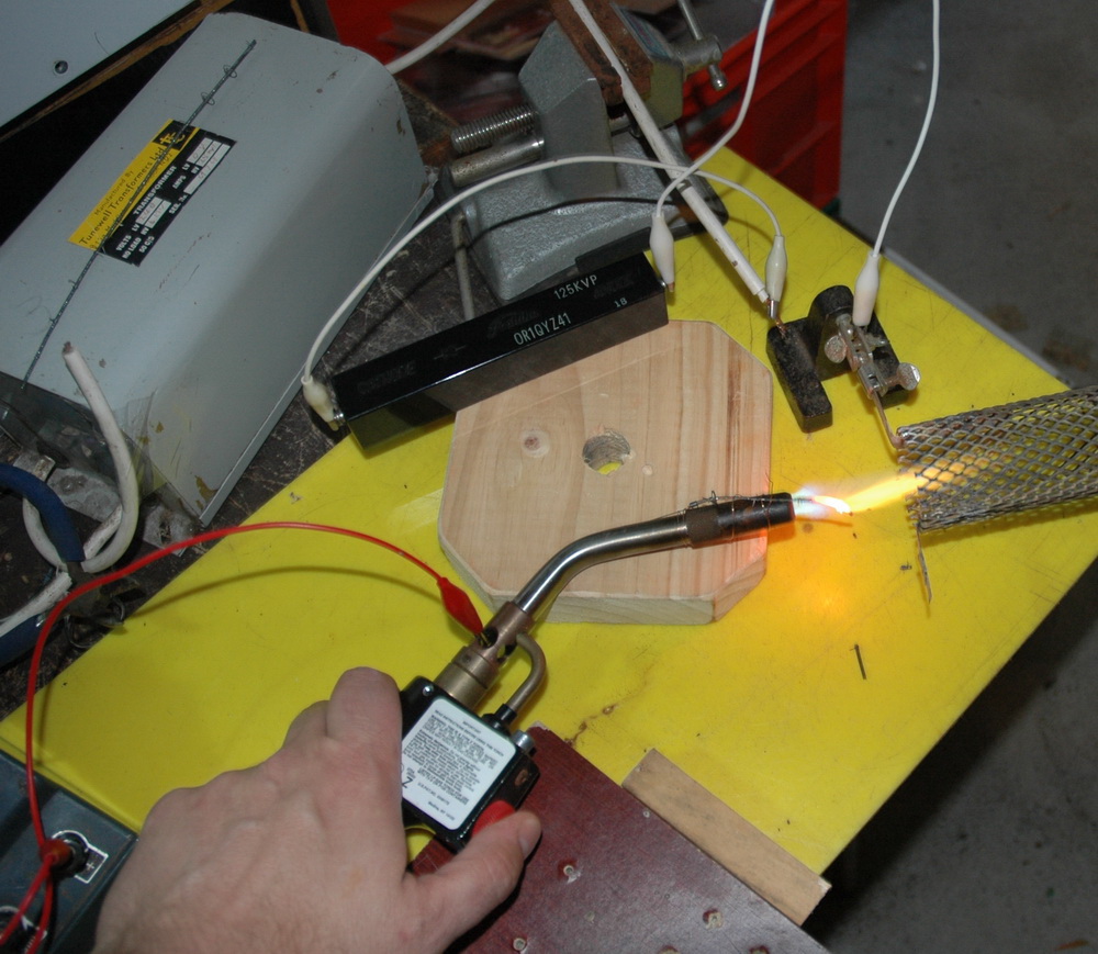
Flame diode
2008
This is a flame and hot filament used to rectify a high voltage in a similar
manner to a vacuum tube. It was based on this excellent
video and
article
where two triodes are made and form a nice oscillator.

(click to enlarge)
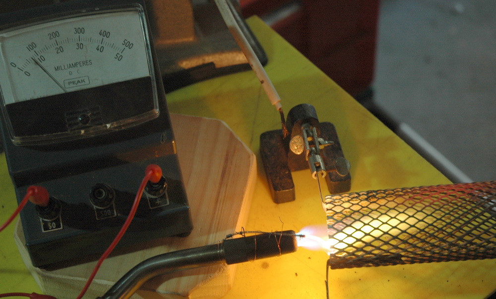
The photos above show the setup with a 6 kV 30 mA neon sign transformer (NST). I am using a MAPP gas burner with a tungsten filament attached to it. The anode is a titanium mesh cylinder from a pool chlorinator. The only time I seemed to get proper rectification was when sparks formed, rather than as a diffuse process as I had hoped. The DC meter shows 7 mA of rectification but it was rather hit and miss and most of the time there was no useful rectification. I am sure the flame position is critical and that the cathode should be fairly cold. It is glowing red hot here.
The tungsten filament oxidises after a while too. I had hopes of making a big propane powered triode to run a VTTC. That would have been impressive.
Probably worth revisiting sometime though, to make a triode with proper grid control. However, I have only ever made only standard valve circuit before so lots of variables even with the flame triode working OK.
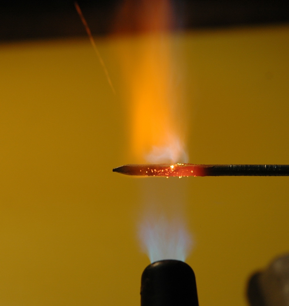
Zinc negative
resistance oscillator 2008
This is based on good articles
here and
here where
they have been used for a transmitter with a 5 mile range. In essence heated
galvanised iron (zinc coated) forms a compound that exhibits negative
resistance and hence can be made to oscillate. Zinc oxide is also used
in MOV's and other electronics.
 (click to enlarge)
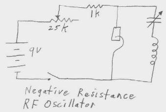
The left photo above show the heating of the galvanised nail until it starts to have sparkles coming off it. The center photo shows the basic circuit with a "catwhisker" contact The right photo shows the setup I used.


(click to enlarge)
The oscilloscope photos show a variety of waveforms when driven by AC 50Hz. The first two on the left show voltage dependent effects and the third shows some rectification. The last shows some 1 MHz oscillation but it was at very low level and I really wasn't sure I wasn't tuning into local AM radio. I never got really stable oscillation with galvanised iron sheet or galvanised nails.
Worth pursuing though. I would love to make a transmitter out of copper and zinc only (including the battery).
Low inductance rolled
capacitor 2008
I was after a homemade rolled cap that would be cheap and reliable enough to
use instead of the expensive MMC's for a Tesla coil. The background is
that a standard rolled capacitor under oil is cheap but messy and fails
readily. I have had many fail.
 (click to enlarge)
Typically they are made of two layers of aluminum foil separated by cheap polyethylene sheeting and rolled up then immersed in transformer oil. Electrodes are attached at one end. The right photo shows one with two caps in series internally.
Recently I developed a better understanding due to two things. Firstly an autopsy of the caps showed that they failed on the innermost tightest turns, the furthest away from the electrode wires. Secondly that this could be understood in terms of the operation of a spiral line generator where voltage is multiplied towards the end of the turns by many times.

 (click to enlarge)
The photo above shows the spiral line generator operating like a Blumlein generator making 30 kV from 6 kV. This high voltage at the ends of a roll results in a high voltage and is one reason why my rolled caps failed. The other being voltage stress which can be helped by using multiple small segments.
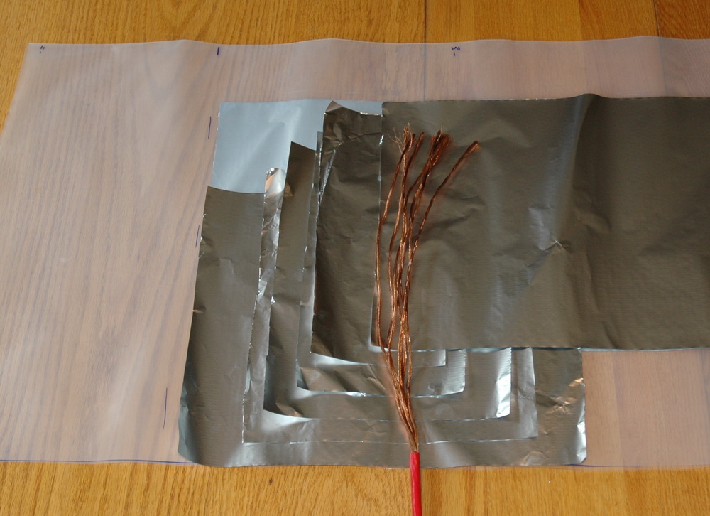
So I went on to make a prototype (1/10 size approx). I found a good way to join wire to aluminum foil and I had 4 segments wound continuously on one roll, so that any currents would inductively oppose and cancel.
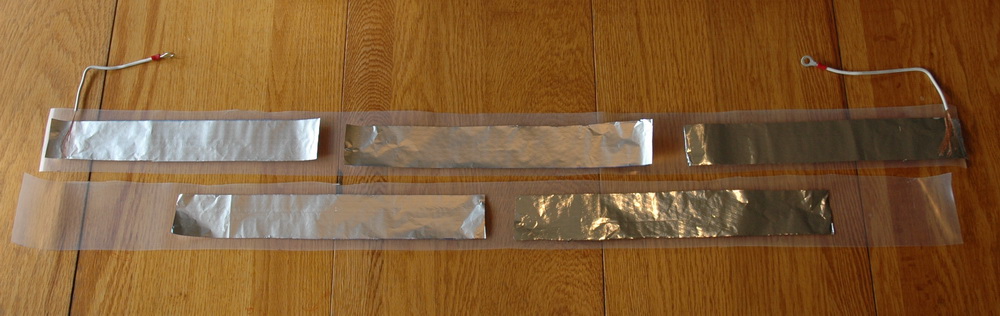

 (click to enlarge)
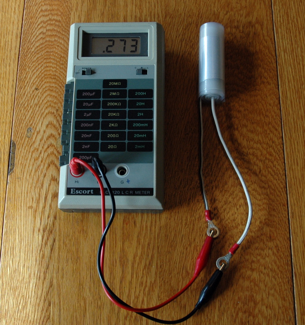
The photos above shows the construction of 4 capacitors in series. The electrodes come from opposite ends to avoid the Blumlein voltage increase and the net current vectors should all cancel giving a low net inductance. There are two main foils which join to the electrodes and 3 intermediary foils to divide the voltage stress giving 4 capacitors in series. The electrodes were solid, capacitance was around expected at 273 pF. It stood off 20 kV easily and stores it for a while. It was looking good. So on to the working model.

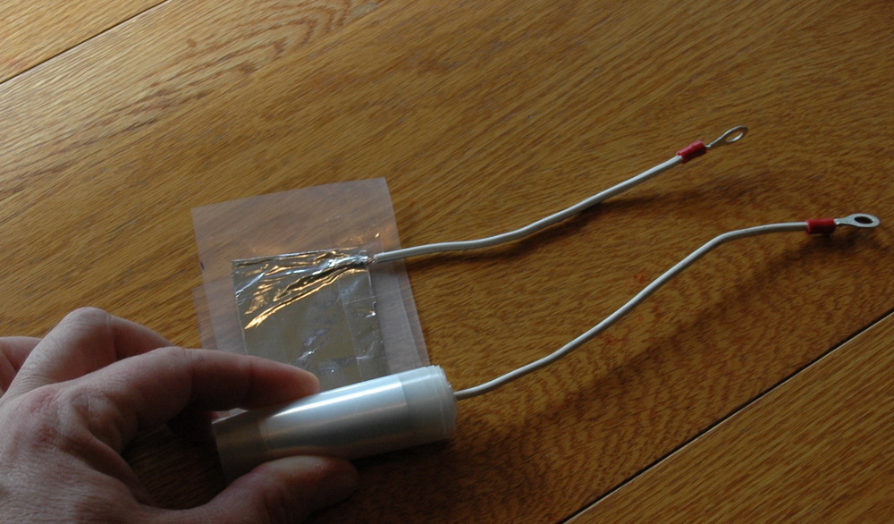
 (click to enlarge)
The photos above show the construction of the electrode attachment with an aluminum foil loop for each small bunch of copper wire strands. The final result as predicted at 26.8 nF. It's a big cap at 2 feet long and I did not intend to put it under oil.
I felt good about this. Smart design for low voltage stress and low
inductance. Hooked it up to my 4 inch coil, puffed out my chest and tried to
tune for a spark....any spark. There was nothing, nada, nix. I
replaced it with a good cap which gave 3 foot sparks to confirm everything
else was OK.
I was completely puzzled. I even unrolled the cap to exclude a short,
checked static DC capability and capacitance and all were OK. I tried to
check the caps self resonant frequency to get a handle on the inductance but
seemed to get equivocal results.
I am still not sure where my design has failed. Presumably the inductance is high and isn't cancelling. I did rewind this on a larger former to have less difference between inner and outer radii but to no avail. There were 30 turns in the original, but I am having trouble getting my head around what is going on. Any ideas?
Levitron
2005
The
Levitron (R) is a
small spinning top like magnet that is fully hovering in mid air
unsupported. It is rather critical in its dimensions and operation and is
adjusted by very small weight changes. It is commercially made and
sold as a toy. See their site for details.
I have tried to make, one unsuccessfully as yet, with the arrangement below.
 (click to enlarge)
Here the magnet is supported in a stable position just above equilibrium. Any lower and it will fall over. If it is spinning and all parameters are correct it would hover in the air until it slowed sufficiently.
I have used a motor to spin it to find a zero balance position but haven't really spent a lot of time on it. Arranging a stable spin as a simple top is the first challenge due to the multiple components (nylon nuts and bolt, acrylic disc and toroidal magnet. I have used a nylon screw but it is very hard to machine as it bends and slips. Probably machining one from something hard like polycarbonate would be better and mean there is only one shaft, disc and magnet support and symmetry is more assured.
Rectifying a Tesla
coil
2007
A Tesla coil has an output of typically 200 kV AC at 100 kHz. To convert
this to DC would allow charging of objects and capacitors. The problem is
that vacuum tubes (valves) to do this are not readily available, nor are
high voltage diodes that can handle the high frequency and voltage together.
It is known that ionic flow in air will be greatest from a point than from a
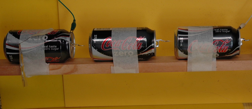
flat surface. To utilize this I have made a setup using soda cans with the
ring-pull twisted and cut to a point. This gives a point to concave
surface from the underside of the previous can. Not only are cans
convenient, but they are rounded and don't have a lot of corona generating
surfaces. To record DC charge, I used an electrometer which is an
ancient device using foil leaflets which separate when charged (with DC
only).
 (click to enlarge)
The photo above shows the setup with two "diodes" in series and shows a spark between 2 of the cans. The left can is earthed and the right can is attached to the output of my miniTC which has an output of about 2 inch sparks at probably 500 kHz. The middle can has a wire supporting the electrometer leaflets which are not separating. Note that sparking will short circuit any diode effect so no DC is expected.
(click to enlarge)
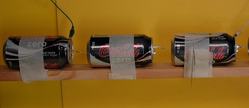
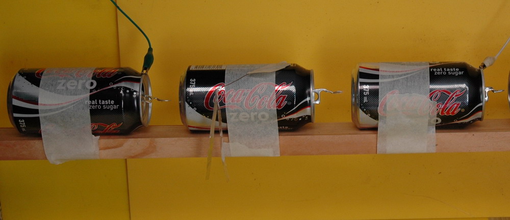
The top photo above shows the electrometer on the left
ground terminal. No charge here as expected.
The second photo shows the electrometer on the right terminal from the TC.
This is AC, so no deflection.
The last photo shows the electrometer on the center terminal. This
should be at a DC potential and indeed with the right combination of input
voltages to avoid sparking, there is a DC indicated by the electrometer.
So is this a success or failure? One problem with this setup is that the TC frequency of my mini TC is so high (~ 500 kHz) that capacitance effects of the cans between each other and in free space may dominate and give spurious results and low output. It was not possible to use this DC to charge another sphere for example. Still the concept is simple, cheap and scalable to higher voltages and bigger TC's with lower frequencies. The cans can be placed in series in large numbers so for a large TC it might just work.
Bear in mind that a TC giving a 6 foot spark would need perhaps 100 cans which would still be a significant capacitance and much larger than the toroid. Also a TC with a 6 foot spark of 300 kV peak when rectified would only be a 1 foot spark when rectified to DC 300 kV as there is no spark growth with DC (at these domestic scales).
Generally speaking it is simpler to use another method to generate high DC voltages like the van der Graaff generator or voltage multiplier.
This page was last updated April 10, 2011